Photo Realistic Rendering
1)Title:- MODELLING OF THE AMERICAN CHOPPER USING SOLIDWORKS.
2) Objective :- To design the fully rendered chopper.
3) Introduction :-
Solidworks is the solid body modelling/designing software that allows us to create a virtual sketch /model of the actual body. This was published by D2S
i.e Dassault Systems on 1 Nov 1995.
Our following project includes an entire modelling of an American Chopper on solidworks software.
Now initially this model deals with the various components :-
- Transmission belt
- Kickstand
- Oiltank and foot pedals
- Front and Rear wheels
- Engine and chassis
- Front and Rear fender
- Chain ,Sprockets ,Caliper , Rim on wheels
- Front Fork and Bar handles
- Exhaust Systems and Air filter
Methodology Flowchart:-
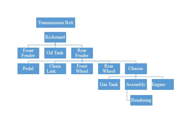
APPROACH TOWARDS DESIGN
This is the most important point where we get to know about the various commands, dimensions and planes. The main thing in approach towards design is the dimension and the parts of the model. Firstly we get to know about the dimension and their units. The units we use for modelling the parts is MMGS and then start modelling with the basic parts of the chopper.
Now initially for modelling /designing the parts we should get to know the basic commands of the solidworks software on which the whole modelling of the chopper is based/depended. The commands given below is used for modelling of the chopper.
- Boss Extrude:- It is one of the initial or we can say the most basic command of the solidworks software. This tool is used to create any 2D sketch (closed) into 3D model by adding materials to the sketch. This command is present in the feature tab.
- Boss Revolve :- This is the command which helps us to add material mostly in circular shape to the sketches. The sketch which is to be revolve must be fully defined along with the axis of revolution. This command is also present in the feature tab.
- Swept Boss / Swept Cut :- This is the feature which helps to create or cut the surface along the desired sketched path but the sketch should be fully defined.This feature helps us to create the difficult geometry like exhaust pipe.
-
Fillet :- Fillet is one of the most handy tool used to give the curve shape/edges to the sharp edges of the fully defined model. This feature gives the model the smoother and the realistic look. This feature is used for finishing purpose of the model.
- Shell :- This command helps to create the solid body or model hollow from inner side, for eg, oiltank but there should be enough material inside model to allow shell command.
- Extrude cut :- Extrude cut command is the important command which helps us to remove material or to provide cut inside the a solid body model at required geometry. This command is also available in the feature tab.
- Linear pattern :- This command helps us to create the multiple instance geometry by just a single sketch but that should be fully defined. This command creates multiple instance in a linear pattern/direction of a single sketch and angle can also be given to the geometry with reference to respective axis.
-
Circular Pattern :- This is kind a similar to linear pattern, but here the circular instances are created on solid model with a single sketch/model.
- This command we can called it a shortcut or the tool that saves the time, if we want to recreate original object of the same dimension equal and opposite to each other this command is used to create the object. This command simply copy the sketch and paste it about the axis to which it is mirrored.
- Reference Geometry :- It is nothing but the plane apart from the main three planes. This planes are used to create the sketch on solid body model where there is no plane or it is also taken as reference for the sketching of geometry.Such reference planes are also used to create the geometry for the swept path like the exhaust of engine.
- Projected Curves :- Curves plays an important in modelling of complex geometry such as to create a path for engine exhaust. The curves are initially made in 2D from the required planes and then projected curve option is used by selecting two curves on different plane and one single 3D curve is projected by the two curves sketches.
- Mate :- This is the option that is basically not used in sketching part but is used in assembly part. This is the basic part of assembly without it assembly cannot be done. There are many types of mates through which assembly can be done like :-
- Coincident
- Concentric
- Parallel
- Angle
- Distance
- Lock
So now after getting the basics of the solidworks software for modelling , now we can see its actual use by applying these features for the chopper model.
The first thing that is initially designed is as follows :-
- Transmission Belt :- The transmission belt model is the single extruded surface of a single sketch with the offset of 3.50mm and fillet of 1.00mm on its edges. The material used on this model is matte rubber.
-
- Kickstand :- In kickstand the sketch was used to create the lofted part throughout the spline and the end parts were domed to give the nice smoothness and curve edges to the end. Again one sketch was created to cut the bottom surface of the kickstand or we can say to make the bottom surface flat to provide the elevation to chopper as well as the surface of the stand should have the proper geometry with respect to the ground. And on to the top of the stand one cylindrical sketch was extruded up to next to provide the clamp to chassis. The material used for kick stand as appearance is chrome (metal).
- Front Fender :- The planes were given reference names as per the requirements of the model. This model is made by using the revolve command in two directions i.e Direction 1 and Direction 2 with the proper angle dimension with reference to axis. Here it is again the single solid body and its edges were filleted to get the smoother look and the material used for the fender is (painted) sienna.
- Chain :- In this part of model the firstly the outer region i.e the outline sketch is designed/sketched with the help of lines and the 3 point arcs. Then just above the outline sketch the front plate and the back plate for the chain is sketched and is saved in the form of the block1 and block2. After that the coincident relation is given to the block with respect to sketched outline or the path created for chain. Then the pins as well as the plates from the blocks is extruded. After that the linear pattern command is used to create the multiple instances of the pins as well as chain plates. Then the fillet is applied to the pins of the chain .Then after creating the one side of the chain the second part i.e the back side of the chain and the fillet is mirrored with reference to the midplane and the chain is modelled.
- Oil tank :- The oil tank is sketched on the top plane and then extruded in the above direction. Now just to make the appearance of the oil tank one more sketch is made at the midplane and extruded. Then all the extruded parts are combined together and then the shell function is applied to the oil tank. Finally the fillet is given to all the sharp edges of the tank just to get the smoother and realistic look.
- Pedal :- Here firstly the base is sketched on front plane and then it is extruded. Then the circular pins is sketched and extruded at the back side of the base for the clamping on the chassis. Now the second sketch is made on the front of the base for the foot rest i.e on the top plane and then revolve it around center axis after that the dome is applied at the front face of the foot rest. Then again the circle is sketched at the base of the pedal and is offset from the surface then the circular pattern is given to get the grip on the foot rest and avoid slipping and, finally fillet is applied to avoid the sharpcuts.
- Front and Rear Wheel :- Here basically the design of the front and the rear wheel is same and based on same concept but the difference is of the dimension and the accessories. Here the sketch is made on the right plane and revolve around the axis from the origin so we get the hub and the circular frame of the wheel. Then again the second sketch is made on the right plane and now the rim is designed /sketched and extruded from the midplane. Now to give the spiderweb design spokes again the sketch is made on the rim using the spline on the front face. And after that the remaining area except the sketch is cut extruded from the rim. Now to give the internal curve shape to the spoke revolve cut is made from on the right plane i.e from front plane. Now to design disc and caliper the design sketch is made on same plane and is offset it from origin to the front of the spokes design and is extruded. After again the sketch is made on the disc to make circular holes and then the linear pattern is given to circles and the extrude cut option is made and after that the circular pattern with the instances, of the extruded cut command is made on the disc. Now the caliper is sketched on the disc and is extruded from the midplane the chamfer is applied to the caliper to get the realistic look and then the fillet is applied.
-
Rear Fender :- The design of the rear fender is same as the front fender just the difference is of the dimension. Here the same revolve command is used in two direction i.e Direction 1 and Direction 2 with proper angle dimension with reference to the axis. Finally the fillet is applied and the material used is again the same as front fender painted-car-sienna.
- Chassis :- The design of the chassis starts with the curves that are drawn on the two different plane and are projected to make a one single 3D curve for the lower part i.e the base of the chassis after that the whole geometry of the lower part is mirrored with reference to the midplane. A sketch is made from the open end of the chassis lower geometry and a square block is extruded. Then the back rod for the rear axle is designed using the splines with the proper dimension. Again one more sweep is made from the back plate of the chassis to the front for the upper design and to provide the support of the gas tank. Now the two geometries are created for the attachments of the pedal and the kickstand. Finally the unwanted material is cut extruded from the part model is the fillet is provided to give the smoother and the realistic look to the chassis. The material for the chassis used is sienna.
-
Front fork :- The front fork consist of the various parts including in itself the various components are made on various planes of the part. The idea to draw the component is to draw the one side of the component and the simply mirror it from the respective plane. Firstly the cylindrical revolve is done to make the long cylindrical part of the fork that will be attached to the front wheel. After that the handle of the chopper using the curve is extruded. And then the brake lever is extruded by sketching on the front face of the handle. The brake wire is sketched and is extruded with proper dimension. After that the headlight is created using the spline using the side plane and the revolve is provided to it by giving the curved sketch it to make it realistic in look. Finally the fillet is provided to all the parts to avoid sharp edges and the whole geometry is mirrored along with the fillet to other side with reference to the axis and then the last step is to combine all the parts along with the mirrored part as on single. The material used for the front fork is chrome metal.
-
Engine :- Now here the engine is not the single entity to draw it whole in a single sketch. It comprises of the various other components like the motor, the exhaust system. Now firstly the sketch is made in the front plane and the design of the base motor is extruded along with the several boss extrude just to make a proper shape of the engine motor. Then at the back the upper curved part is extruded and is filleted to avoid sharp edges and to get the proper shape. Now at the back face of the engine two revolve is created for the arrangement of the transmission belt. The square teeth design is extruded on the face of the circular region up to next and the circular pattern is created on both the motors just to get the grip to the transmission belt and reduce friction produced.
Now the upper case of the engine i.e the place where the piston is actually located is sketched on the top plane on the upper side of the engine one small and one big size square type structure is extruded and then both are linearly patterned for the fins structure then the fillet is provided to avoid the sharp edges and get the smoother look. Then the sparkplug sketch is created and extruded. And then whole geometry along with fillet is mirrored by the reference axis and the two cylinder engine is designed. Now the end sprocket is designed and extruded for the purpose of the power transmission to the rear wheel with the help of chain links. Then the intake valves are designed using the reference geometry plane and only one side is sketched and extruded then the other side is mirrored from the reference plane. Then the air filter is designed using the spline and swept boss command is used to get the air filter structure and then the offset is used to get the cut structure on the air filter and then the circular pattern is used to create the multiple instances.
Now the final part is to design the exhaust and the spark plug cable to design the exhaust the curves are sketched on different plane according to the design and then the two curves are merged i.e they are projected and one single 3D curve is obtained now to create the geometry for the path to travel one refrence plane is made with respect to the projected curve and is swept boss along the curve and the exhaust of the engine is fully designed. Now for the spark plug cable the sketch is made on the top face of the spark plug and is again swept boss along the sketched spline same is done with the other sparkplug and the engine is fully designed. Finally the fillet is applied to the sharp edges to get the smoother look.
-
Gas tank :- The gas tank is the final part to get designed this part is sketched on the front reference plane using the 2D splines and then by dimensioning the sketch the surface sweep command is used and the upper surface is done then the surface trim option is used in order to give the shape of the gas tank. Then to make the closed surface from the front the curve is sketched on to the second reference plane and the surface loft command is used and the require geometry of the tank is achieved from front of the tank. Finally again the geometry is made to attain the final structure of the gas tank using the 2D spline and the boundary surface option is used to complete the geometry. After that the whole one sided part is mirrored using the reference plane and the seat is designed and extruded then the fillet is applied to it to give the realistic and the curved shape to it. Finally the last sketch is made to provide the geometry for the upper portion of the chassis so it is sketched on the reference plane and the surface swept cut command is used and geometry is created finally the fillet is used to look surface smoother and realistic.
-
Assembly :- Now that we have designed all the parts of our chopper the main part comes here is of the assembly work. The assembly is to be start with the chassis because it is the base and the main part of the model. So now the chassis is initially placed in then it is fixed at the one position in order to avoid the floating of the chassis. Then the engine part is brought and the coincident relation is made of the engine front plane and the mid plane of the chassis. So now the engine is coincident with chassis now the lower legs of engine is made coincident with the centre plates of the chassis so now the engine is placed but as it comes out of the plates the dimension is provided the engine with respect to chassis and is fixed at one place. Now the pedals are to be clamped at the chassis so the internal circle of the clamp plate is made concentric with the outer edges of the pedal then the surface of the pedal and the surface of the clamp plate is made coincident. Now the pedal is to be mirrored on the other side of the chassis so the mirror command is used and here the body is mirrored with respect to the mid plane of the chassis and hence pedal are fixed. Now the kickstand is to be clamped so again the concentric and the coincident relation is used and the kick stand is fixed then the angle dimension is provided to the stand to make the flexible rotation of the stand. Then the transmission belt is made concentric with the motors then the width mate is used to fix the belt on the motors. Then for the oil tank the coincident relation is applied to all the parts with respect to the axis. Then for the rear wheel the mid plane of the wheel is made coincident with the mid plane of the chassis and then the rear axle is made concentric with the hub of the rear wheel. Now the rear fender is made concentric with the rear wheel and then the mid plane of the fender is made coincident with the mid plane of the chassis. Now the chain is brought close to the rear sprocket and is given the width mate then the chain sketch is made concentric with the rear sprocket, and then the top plane of the chain is give the parallel mate with the bottom plane of the chassis. The gas tank top plane is given the coincident mate with the top plane of the chassis and the front plane is made coincident with the front reference plane of the gas tank. Now the front fork is given the concentric mate and the width mate with respect to chassis. Also the angle limit is applied to the handle bar of the fork. Now the front wheel is given the concentric mate and the coincident mate with respect to the front fork. The vertical plane of the front fork is made coincident with the front plane of the front wheel. And also the tangents are also applied to but to avoid the over defining they are just suppressed. And hence here the assembly of the chopper is completed.
-
Rendering :- It is obviously the last and the most important part to work on. Rendering is done to provide the realistic look to our model. So here basically in the render part what is done that the front and the rear wheel are supposed to be grounded to look real so here the tangents are provided with respect to the bottom plane (ground) to the front wheel and the rear wheel. Now to give elevation to the chopper and look more real here also the tangent is provided with respect to the ground on the flat side of the kickstand to avoid the over defining sketch the tangent of the kickstand mate is suppressed. Now to give the look to the chopper the gas tank, oil tank and the rear fender the decals are applied to all three parts of the chopper. Then the background selection process is done to get the best scene for our chopper model and the daytime scene is used. The below given image is fully rendered image using the plain white background.
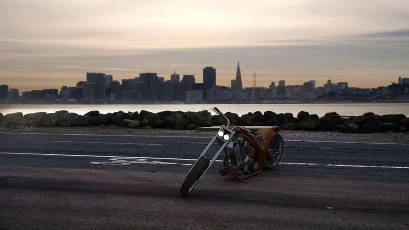
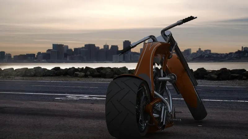
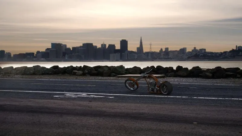
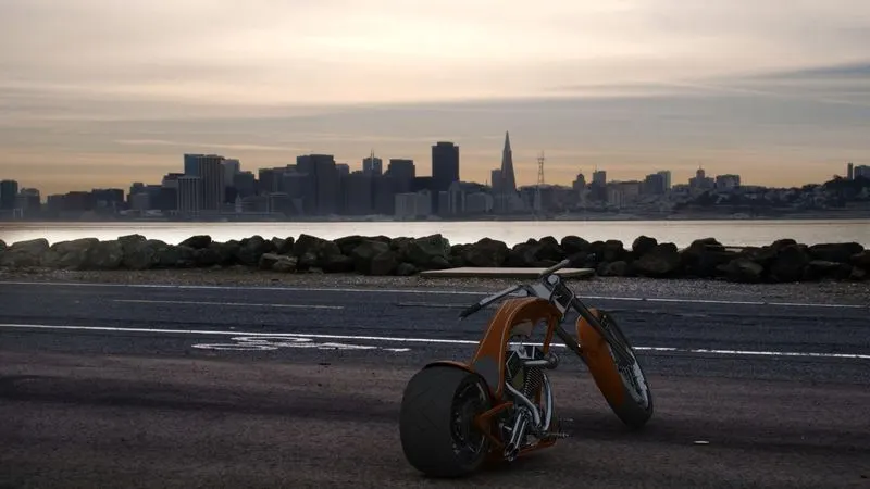
- But now to give the more realistic look and to ensure that how actually the chopper looks in our environment the scenes are added and it is ensured that the chopper should be proper grounded and the kickstand should have proper tangent relation with the ground. And also the lean is provided to the chopper. Here the chopper is kept at different angles in the scene to get the best suited view. After the satisfaction of the position of the chopper in the scene, preview window is used to see how the scene is rendered and then the final render is provided at the maximum render output quality and hence after the final render we get the best and spectacular product.