Week 8 - Challenge 3 - Switch Bezel Design
SWITCH BEZEL DESIGN
Switch bezel is one of the interior part of the automotive, that is to be designed and at last the draft analysis is to be done to find the designed product can be manufactured or not.
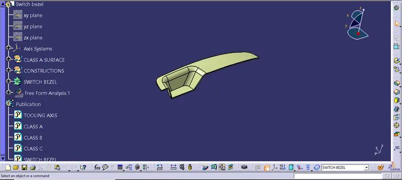
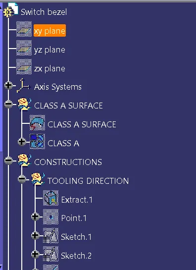
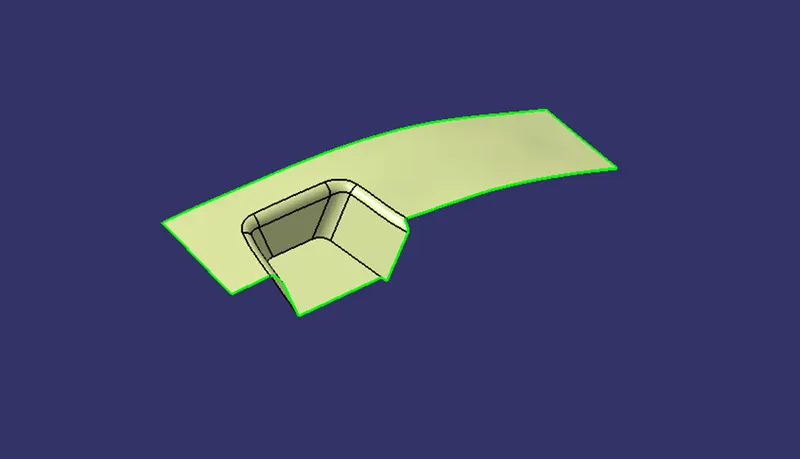
Now the Class A Surface is given as an input of the switch bezel as shown in the figure below.
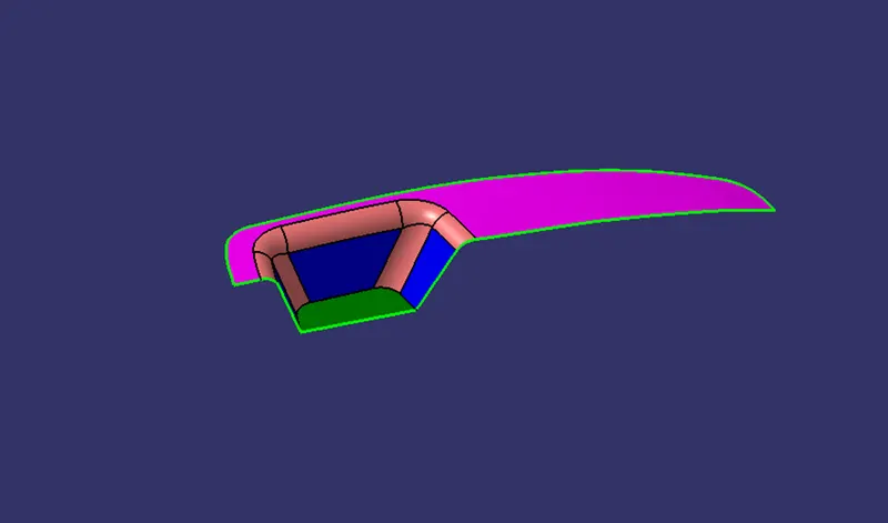
Now the design checks are done based on the plastic product design rules. Initially the connectivity of the Class A Surface is checked using the boundary, join command. If the connectivity has the error then the Class A Surface is been dismantled and again it is been joined.
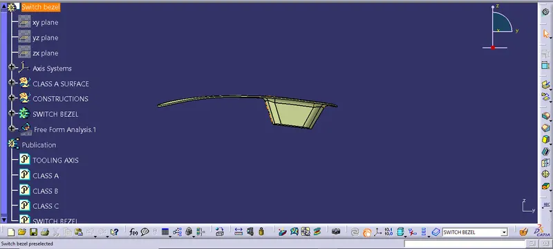
The next step is the direction of the tooling which is the most basic and the important step of the plastic product design. Now it is visually been recognized that the tooling direction should be in the Z direction. Then the tooling in the X direction is been cleared by drawing the two lines and then bisecting them as shown in the figure below. Hence the tooling in the X direction is cleared.
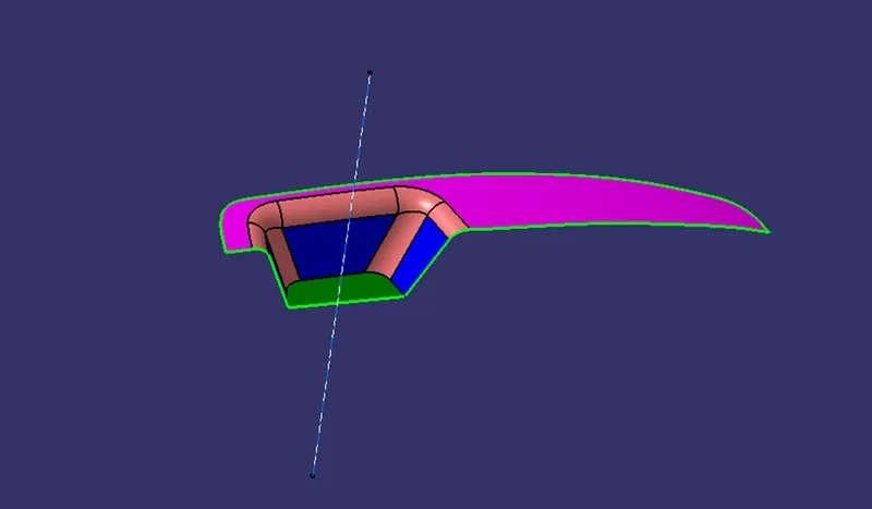
Now the tooling in the Y direction is to be cleared, but the problem here is the Y direction has only one wall. So here the second line is drawn at center but at an angle of 6 degree, to get the bisecting line as shown in the figure below.
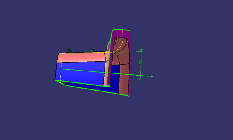
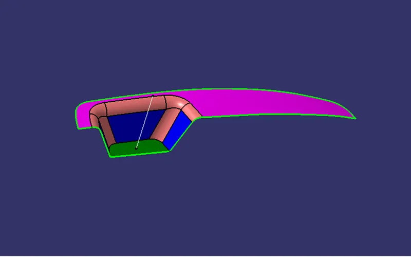
The above line cleared tooling along the Y direction .
Now finally the tooling line clearing X direction and the tooling line clearing Y direction, these both lines are bisected and the line which is formed is the tooling axis, as shown in the figure below.
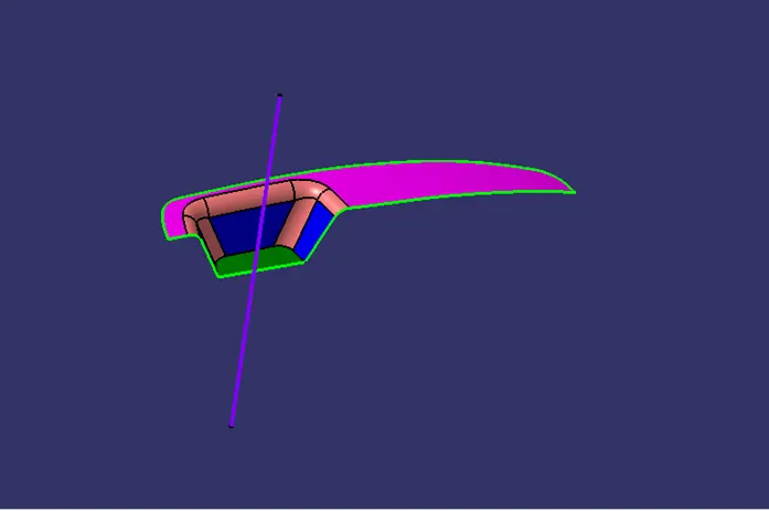
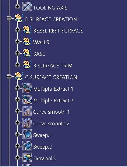
Now as the tooling direction of the component is confirmed, the Class B Surface is to be designed. For the Class B Surface firstly one by one surface is been extracted, then it is been un-trim, extrapolated with point propagation and finally offset with the thickness of 3mm as shown in the figure below.
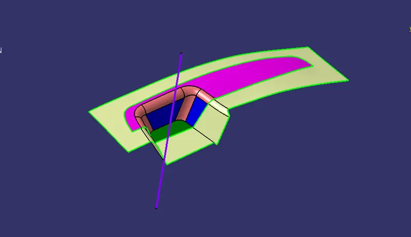
The surface below the Class A Surface is the Class B Surface.
As the surfaces are offset, the trim command is used to remove the excess faces and then the fillet is given. But to attain the proper thickness of the component and to avoid the uneven material filling in the mold, the fillet value is given as follows. Fillet value of the two corners is 15mm, it is given as it is, but the upper edge fillet value is 14mm so to attain the proper thickness it is given as -: fillet value – the thickness of the component ( i.e 14mm – 3mm = 11mm ).
Hence our Class B Surface is designed.
Now the design of the Class C Surface is to be done, which is the surface that closes the Class A and Class B Surfaces together.
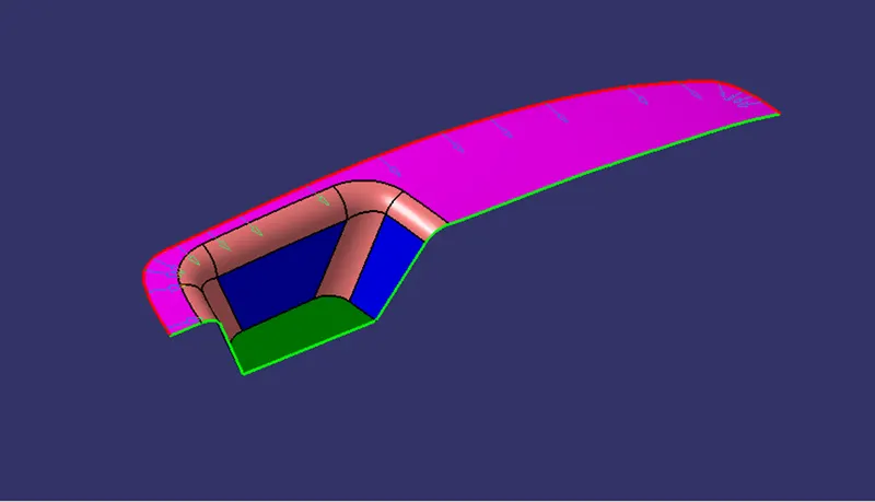
Now for the Class C Surface the one side of the Class A Surface boundary is extracted at once and then the other side of the Class A is extracted as shown in the figure below.
After the boundary is extracted both the extracts are converted into the smooth curve as both the boundary contains many uneven joints which may cause the problem during the sweep. The figures are given below -:
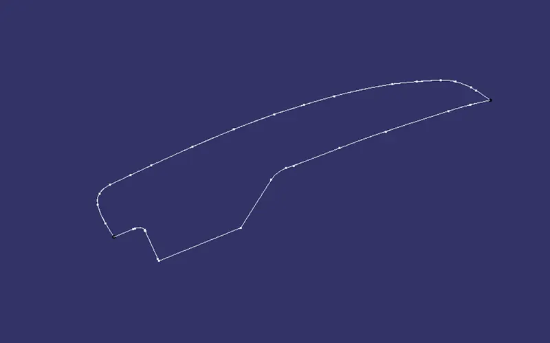
The extracts of the boundary.
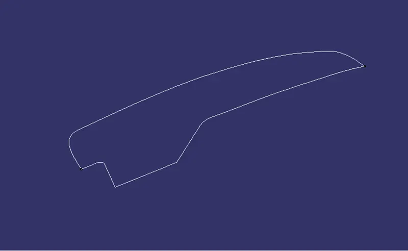
The boundary after turning the curves smooth.
Now as the curves are smooth, the sweep is performed along the draft direction at 3degree downward. Then these sweeps are extrapolated from both the sides and then the final trim is performed to make the Class C Surface join as shown in the figure below.
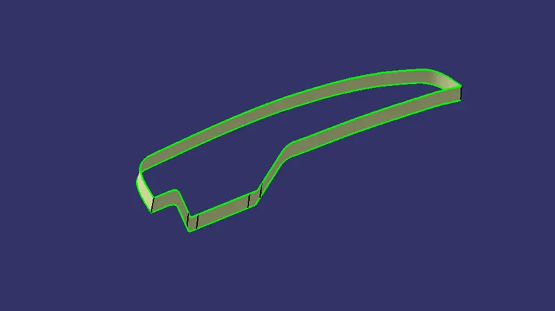
Now all the surfaces are ready. The final task is to do the final join i.e to combine all the surfaces. Here firstly the class A and the Class C Surfaces are join together. If the surfaces are still not join then just extrapolate that part of the surface. And then finally the final trim is performed with Class B Surface and hence the part is ready as shown in the figure below.
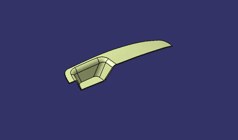
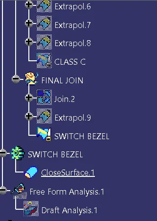
Now to convert the surface design into the solid model. So go into the part design and then define the partbody and then select the close body command and select the component and click ok. Hence our solid body is ready as shown in the figure below.
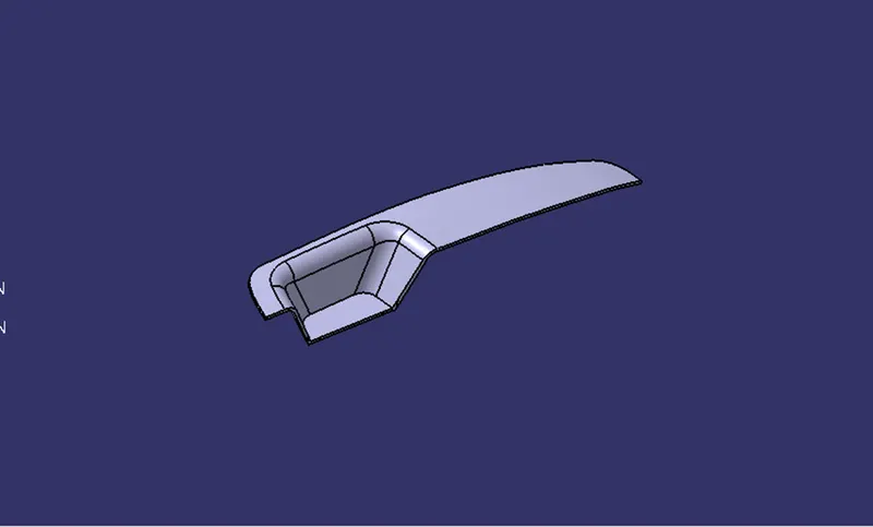
Hence our solid body is ready.
But now it is to be ensured that the designed product can be manufactured or not. So the draft analysis is performed on the component.
Initially the material is selected from the customize view parameters then the draft analysis toolbar is opened. Firstly the compass is placed on to the direction tooling axis and then the component is selected as the component is selected the inner side of the part turns green except the right face of the part. As we gave the nominal draft 3 degree, the right face turns red i.e it have the value in between 0 and 3. So to solve this problem the value of the draft is kept 2.9 degree and hence the draft analysis gets completed as shown in the figure below.
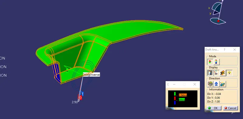
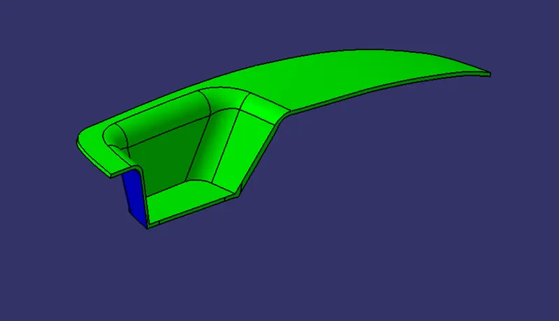
Hence the draft analysis is completed and the product can be manufactured.
IMAGES :-