Radar Mast & Final Assembly of Yacht
REPORT OF THE YACHT
MODELLING OF YACHT USING SOLIDWORKS SOFTWARE
Introduction
In the earlier project of the solidworks we have modelled the American chopper using the solid modelling, but now in this project we are going to model the yacht using the surface modelling in the solidworks software.
There are various different components of the yacht that are as follows:-
- Propeller
- Radar
- Blueprint Setup
- Hull
- Garage Door
- Front Seat
- Middle Seat
- Rear Seat
- Superstructure
- Radarmast So the above given are the components of the yacht that are modelled one by one using the surface modelling and finally the assembly is done long with the rendering part to give the original and the realistic look to our yacht.
Design Approach
The approach of the design towards the yacht model is given in the flowchart as follows :-
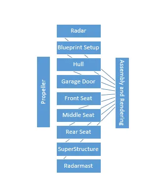
- PROPELLER:- Propeller is one of the important component of the yacht model. The purpose of the propeller is to carry forward the yacht by creating the thrust in the opposite direction of the yacht. The propellers are also used in the aeroplanes and many other places.
Now in modelling this part various commands are used we will get to know about it one by one :-
1. Revolve:- It is one of the most used command in the solidworks. It is used to make the circular profile solid along the preferred axis. Here in the propeller initially the sketch is made and then the revolve command is used to make the main base hub of the propeller.
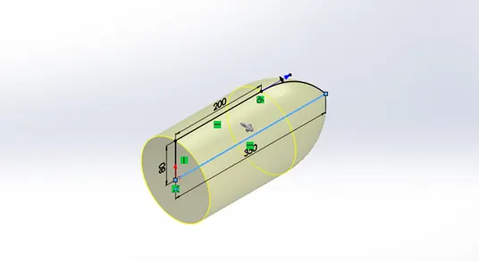
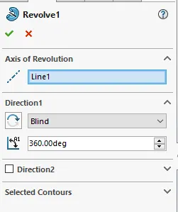
2. Loft:- The loft command is use to create the complex geometry structures between the two sketches. Here the two sketches are selected in the loft profile and the guide curve is left empty as the loft which is performed is solid body loft.
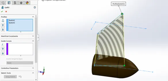
3. Fillet:- Then the fillet is applied to the two upper edges of the lofted profile.
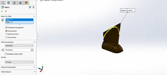
4. Cut Extrude :- Then the cut extrude is done to provide the space for the hub to get fixed in between the propeller.
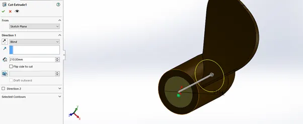
5. Circular pattern :- It is the command that is used to create the circular instance along the circular profile. Here the number of the circular instances given to the propeller blade is 6 along the outer circular profile.
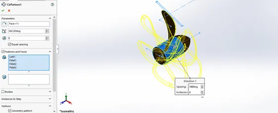
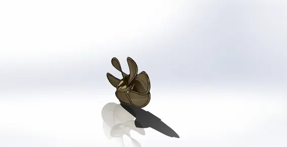
Hence the propeller is fully designed and modelled.
- RADAR:- It is another most basic component in the yacht that helps to navigate the route to find the best possible route for the yacht and also helps to avoid the bigger obstacles like the rocks etc… here the radar is designed using various command available in solidworks.
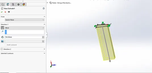
- Boss Extrude :- Firstly the sketch is drawn that resembles the radar shape and then it is extrude about 700 mm.
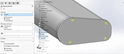
2. Sketch Driven Pattern :- After doing the boss extrude the sketch driven pattern is used to make the replica of the single sketch into the other three as shown in the figure below.
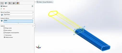
3. Mirror :- Then after filleting the edges of the radar and giving the smooth texture to the edges the mirror command is performed to make the component look like the radar.
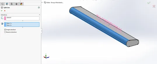
4. Split line :- It is the command that is used to project the line on the irregular surface or we can say to project the line on the circular or the curve face of the component.
Hence the modelling of the radar is complete.
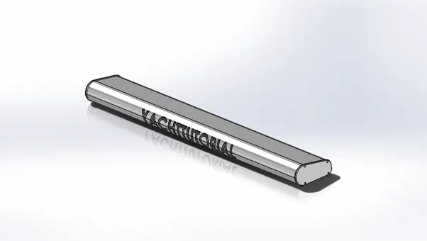
- BLUEPRINT SETUP:- This is the basic setup for the entire modelling of the yacht, it includes the front, back, top, bottom and side view blueprint of the yacht.
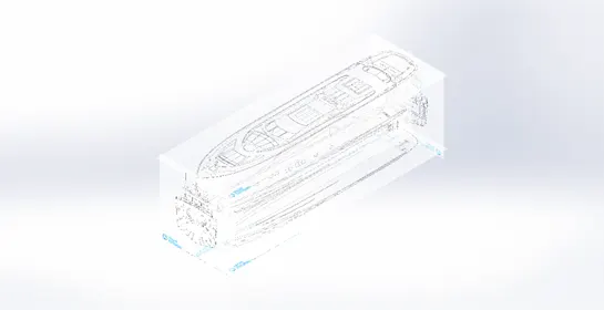
- HULL:- Hull is the most important part of the yacht it is the ship like structure that helps to store the important and necessary things that are required in yacht like machinery, lifejackets, long space to move along the entire yacht along with the infrastructure i.e the seats to get relax.
While modelling the hull various new command is used we will get to know about it one by one, and also from here the surface modelling starts i.e the whole hull is modelled using surface commands.
- Project Curve :- It is the initial step of the hull design, firstly the two sketches are made that resembles the hull design using the blueprint setup and then the project curve option is used to make the smooth curve for hull.
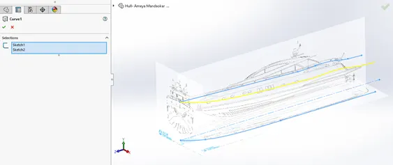
2. Surface Loft :- As the curves are uneven so here the surface loft is used to create a smooth surface structure. Here the two sketches are selected for the guide curve as shown in below figure.
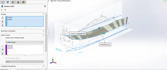
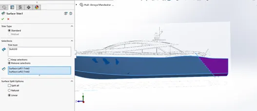
3. Surface Trim :- To give the structure of hull that resembles like the blueprint setup surface trim is done by drawing the sketch and then trimming the surface as shown in the below figures. Here the surface trim tool used is the recent sketch from where we have to trim then go for remove the selections option and the select the two surface select the linear option and then click ok.
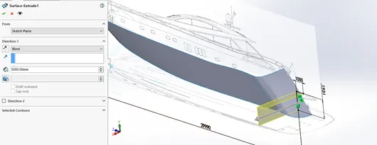
4. Surface Extrude :- Till now we have been using the extrude boss base option to create solid base but here the surface extrude option is used at the end of the surface after surface loft, to create the closed profile from backwards.
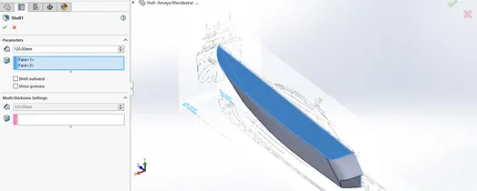
5. Shell :- Here the shell option is used to create the part of the hull hollow from inside in order to make space inside the hull and also to give the desired thickness to the surfaces.
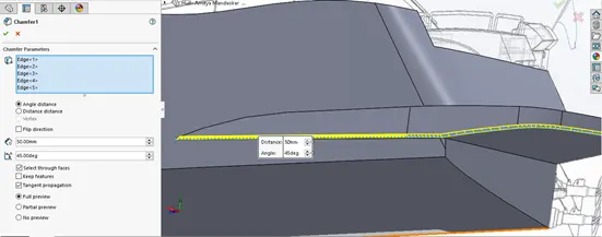
6. Chamfer :- Chamfer is the command tool that is used to make the surface edge, face, vertex get chopped at an angle as well as distance.
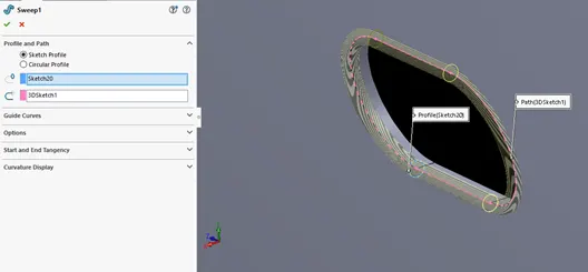
7. Sweep Boss:- Sweep command tool is used to create any desires sketch along the path, here the sweep command is used to create the solid sweep for the windows structure.
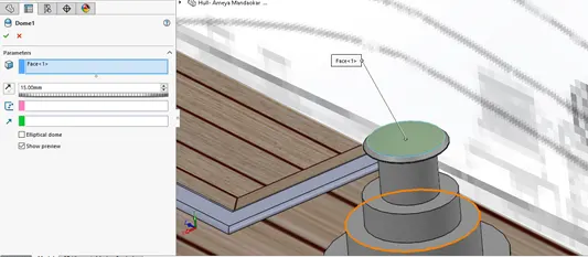
8. Dome :- Dome is used to create the curved shape to the plane shape of the structure as shown in the below figure.
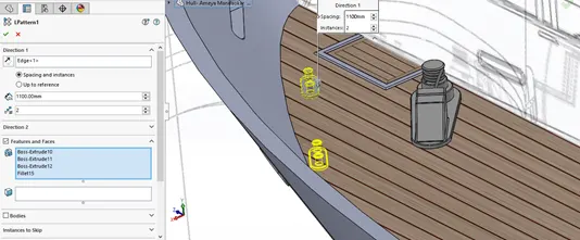
9. Linear Pattern :- Linear pattern is used to create the multiple instances pattern of the single body in linear direction as shown in the figure below.
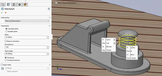
10.Helix/Spiral :- Helix/spiral is the command which is used to create the spring structure for the small component of the hull as shown in the figure.
11. Delete face :- This command is used to delete or to keep the unwanted body of the component as shown in the below figure.
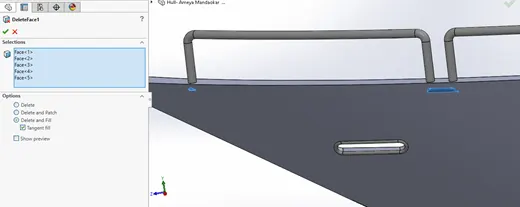
Hence after using the above commands the model of the hull is ready.
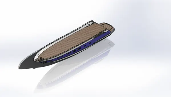
- GARAGE DOOR :- Now as we know that the modern yacht are used as the luxury which definitely includes the super cars these garage door is that kind of thing which helps to keep the bikes and super cars. This door is operated electrically to be open and closed this door is modelled using the same commands as shown in above parts.
- SUPERSTRUCTURE :- It is the infrastructure part or we can say the advance and the main part of the yacht which is situated at the center of the hull. In the above hull part we have studies various commands of the surface modelling the remaining commands will be seen in this part of the yacht one by one.
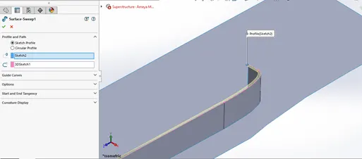
- Surface Sweep :- It is the basic part or command to create the superstructure model. If any of the relation like coincident, pierce is created in between profile in the guide curve the surface sweep creates the surface along the sketched profile.
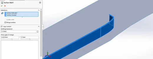
2. Surface Knit :- Surface knit is one of the important feature that helps to knit i.e helps to reduce the or close the gap between the surfaces the value used is 0.10 mm.
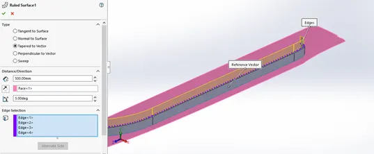
3. Ruled Surface :- We can called it as the one of similar command to the surface extension but here the edges are extended at an angle in order to create the geometry according to the yacht. It has various commands options like tapered to vector, tangent to the surface and so on as shown in the figure.
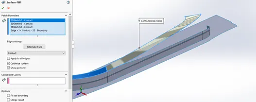
4. Surface Fill :- This command is used to create the smooth surface between the entities i.e the remaining gaps or the closed sketch can be filled using this command. Here in the yacht the two curves are filled with surface using surface filled command.
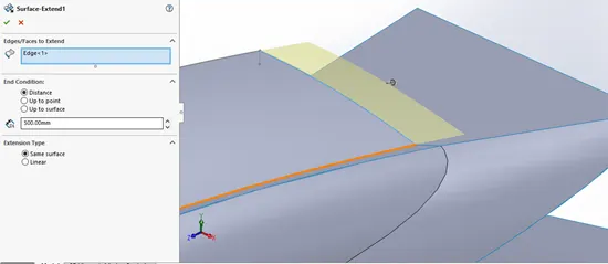
5. Surface Extend :- Here this command is used to create the closed profile between the surfaces, firstly the surfaces are extended and then the surface trim option is used to trim the surface and then the surfaces are knitted to ensure 0 % gap between them.
However after completion of the one side of the yacht all the surfaces are knitted with the gap tolerance of 0.10 mm then other side of the structure is mirrored with respect to the midplane by selecting the all the options merge entities, knit surfaces and propagate visuals as given below.
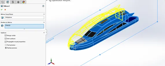
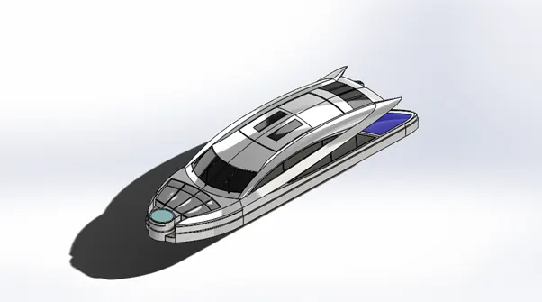
Hence then the wipers of the superstructure are modelled and then the material color are added according to the structure and our superstructure is fully modelled.
- Front Seat :- The front seat is located at front of the Jacuzzi of the superstructure. This seat is created using the same commands and tools. Here initially the one side of the seat is modelled and is filleted, then it mirrored along the other side across the midplane.
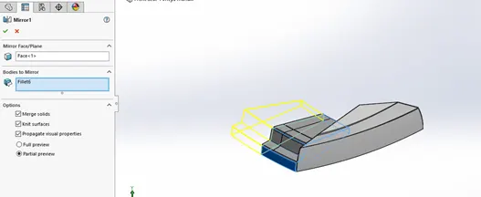
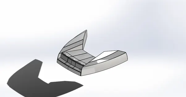
In the above figure the mirror of the seat works one by one to each part and hence the final front seat is modelled as shown below.
- MIDDLE SEAT :- The middle seat is designed in such a way that the table is at the middle and the seat is surrounded by the three side of the table. This seat is designed in the same way using the same commands, initially the sketch is extruded then the fillet is applied along with the chamfer. Same as the front seat the one side is designed of the middle seat and then it is mirrored to the other side of the plane.
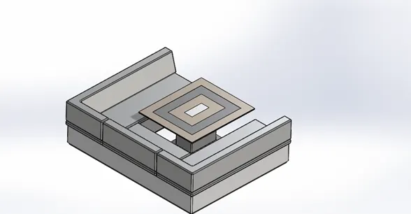
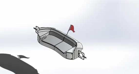
- REAR SEAT :- Here the same procedure is applied only one side of the seat is designed and the other one is mirrored. But here the flag is created using the splines and then the surface loft command is used to fill the flag. Hence our rear seat is fully designed.
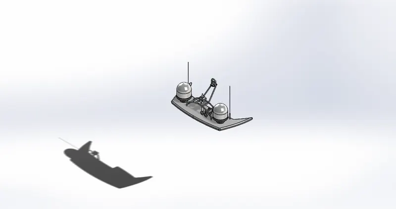
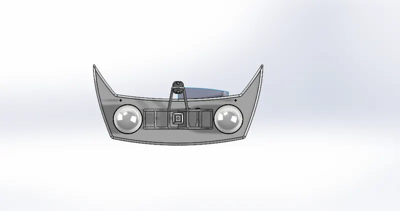
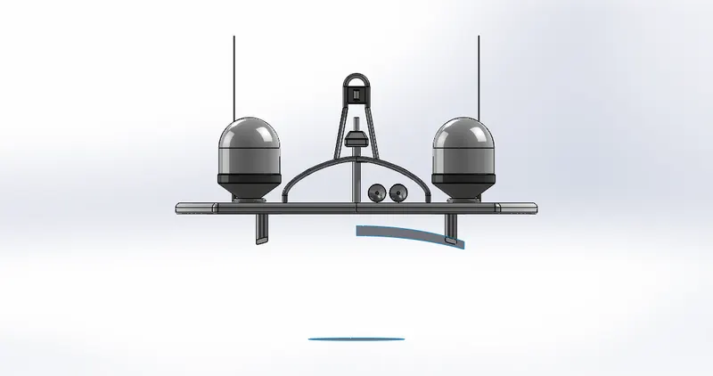
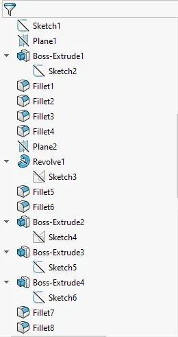
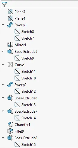
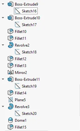
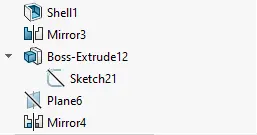
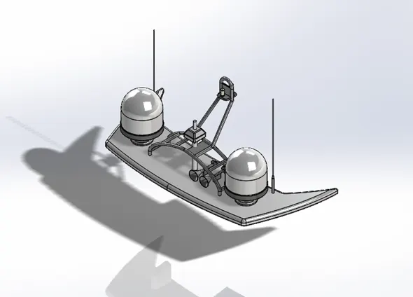
- RADARMAST :- The Radarmast is one of the most important component where the radar is mount along with the antenna that are used to transmit and receive the signals. It too has the horns mounted on the radarmast. The model of the radarmast is given below.
ASSEMBLY OF THE YACHT
Assembly is basically the combination of the parts modelled and are arranged in such a way that after combining the parts it becomes a whole machine which is used to do the certain tasks by reducing human efforts.
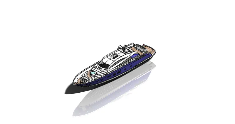
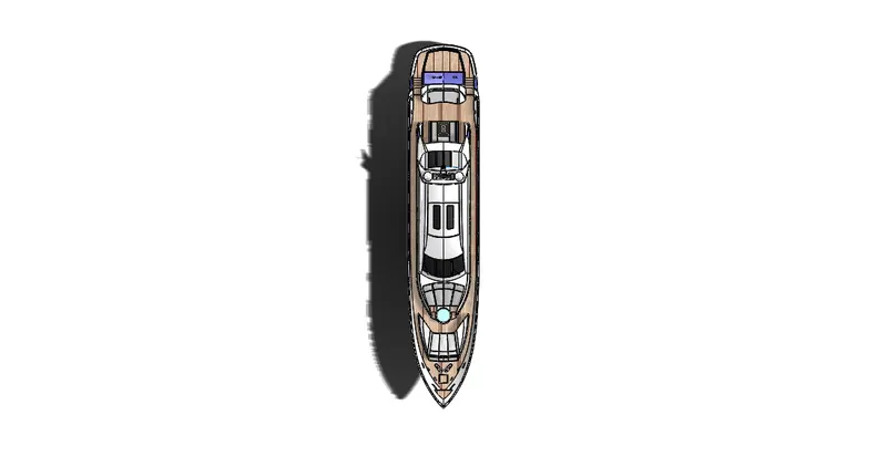
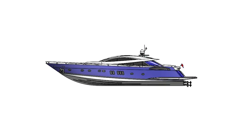
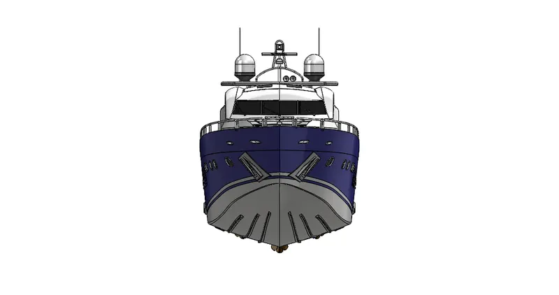
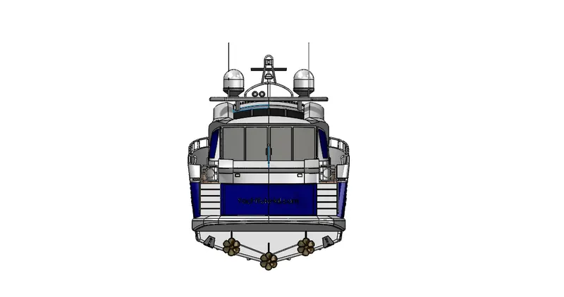
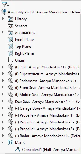
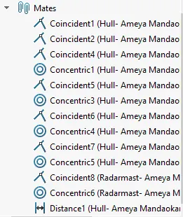
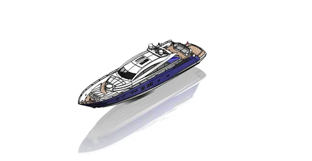
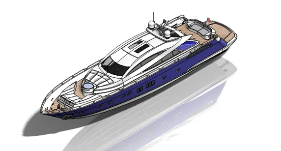
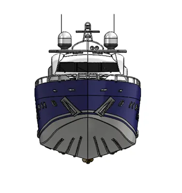
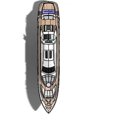
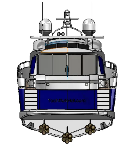
Here the assembly done is very easy what actually done is the assembly part file is open from the solidworks then the base of the yacht is open i.e the hull is open and then ok is clicked. Then again the part is inserted that is the superstructure again ok is clicked the superstructure is placed on the hull at the exact position. Then the front, middle and the rear seat is inserted and the assembled on the hull. Then the radarmast is inserted and it is placed on the superstructure. Finally the garage door and the radar is inserted and are mounted on the hull and at the final we get our fully modelled yacht as shown in the below figure.
- Isometric View :-
2. Front view :-
3. Top view :-
4. Back view :-
PHOTOVIEW 360 RENDERING
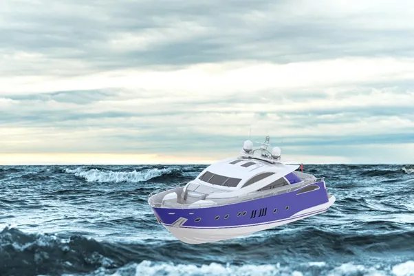
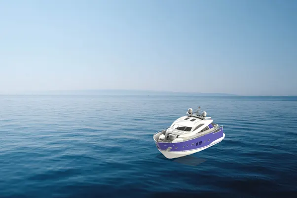
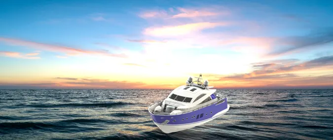
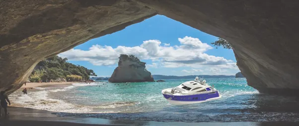
Rendering is the final part and final step of this project that helps us to give our model the realistic view. Rendering part includes the applying of the decals, lighting, scene, and environment.
In the rendering process start with add ins then turn on photoview 360 after the go to edit the scene select the best suited scene for our yacht then select the environment in which we need the yacht and then go to the advance lighting setting and change the brightness of the model as well as the scene. And at last we get the final render of our yacht.
RENDERED IMAGES