Week 9 - Project - Master Section Development
AIM:
To create a solid body of B pillar cover including ribs and locators by using given Class-A surface.
OBJECTIVE:
- Tooling Axis creation
- To create B surface
- To create a C surface
- To create a solid part
- Draft analysis
- Create a dog house
- Create a 4-Way locator
- Create a Rib.
GIVEN CLASS A SURFACE:
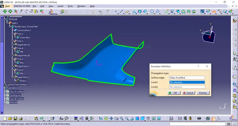
First I need to check whether the surface has some boundary irregularities and any open boundaries.
Tooling axis creation:
The Tooling Direction is basically the direction that the mold pulls apart. The mold is built in two separate pieces, basically. You have a Cavity side and you have the Core side. The Core pulls apart from the Cavity and that's the Dyeline or the Tooling Direction.
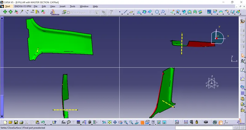
- analyzing the model visually to see the most efficient side suitable for the tooling axis from the image below image.
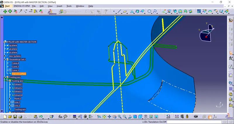
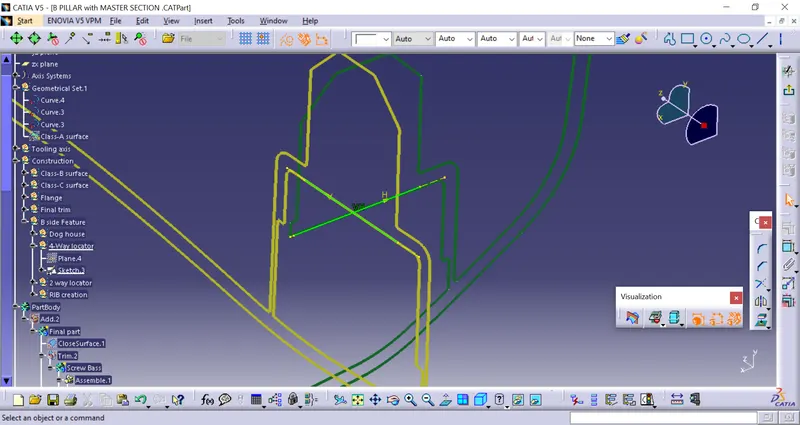
By taking the intersection line between the 4-way locator by bisecting lines to form a Tooling Axis.
CREATING CLASS-B SURFACE:
By Offset the Class-A surface by 2.5mm to form a class-B surface.
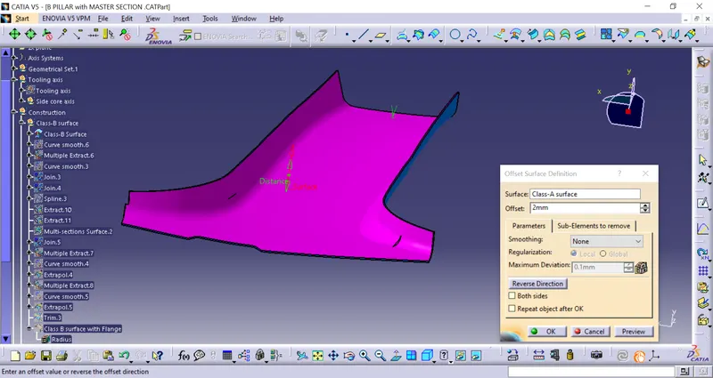
By using multiple extracts create the boundary to create sweep and extrapolate the corner surface to trimming with sweep and form Final Class-B surface.
By extrapolating the edges from class B.
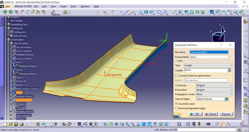
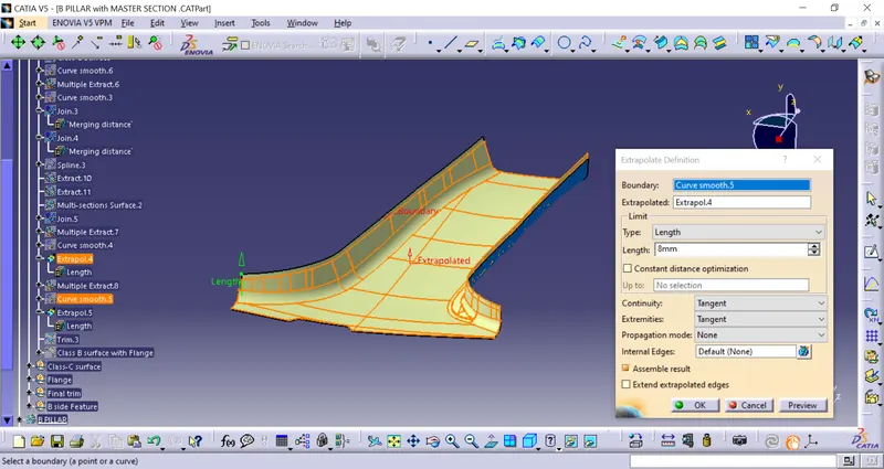
Extrapolating the opposite corners.
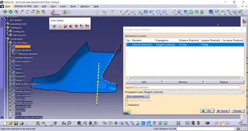
Creating a boundary using multiple extracts it gives more edges to avoid edges we need to convert multiple extracts to smooth edges.
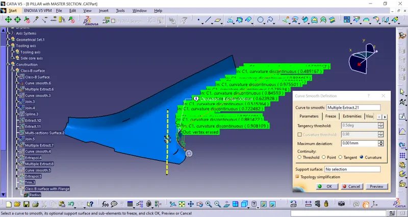
Now create a sweep to form a flange on both sides.
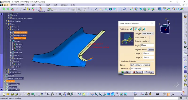
After sweep trim the flanges and extrapolate to form a final out put of the class-B surface.
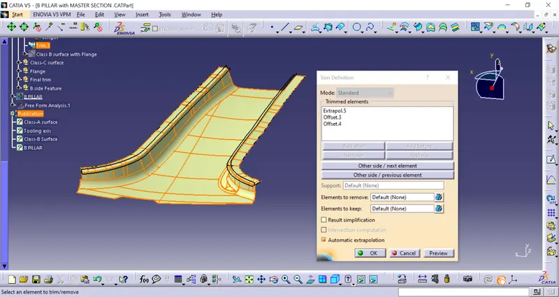
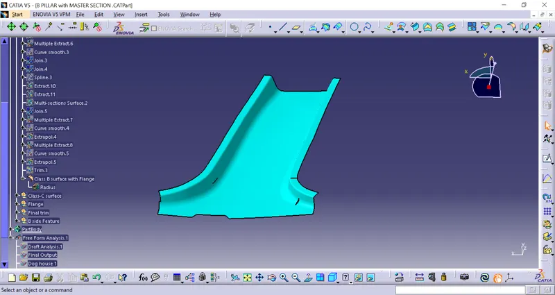
Creating Class-C surface:
By extracting the boundary from the Class-A surface required for class-C surface. sweep the boundary with respect to the class-A surface, and trim Class-A with a sweep to combine, next trim class-C surface with the class-B surface to form the final output.

Now sweep the all boundary to y-direction ane angle always turned inward drafting.
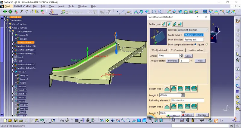
after trimming the all sweeps with class A to form class C surface.
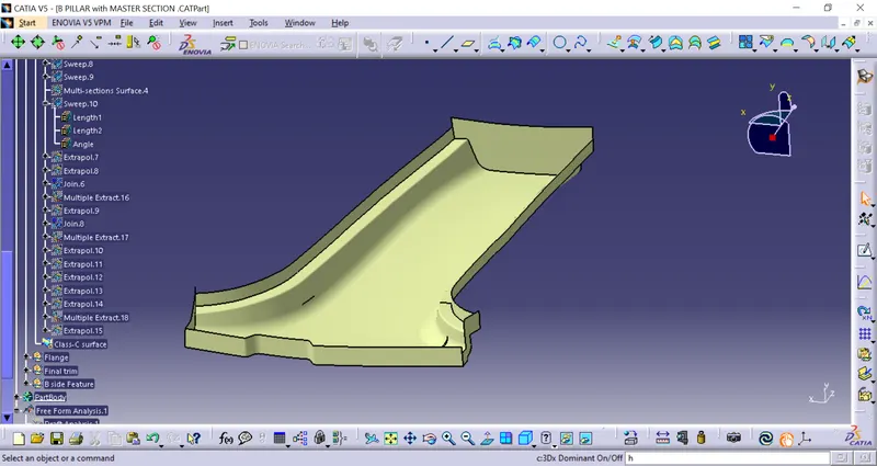
To form A final output we need to trim both Class-B and Class-C surfaces to get the final output.
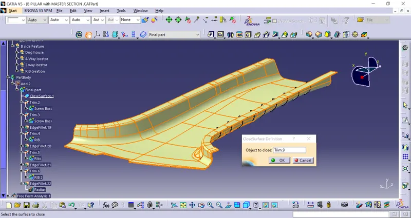
Final output:
After getting the final output goes to Partworkbench to convert the closed surface.
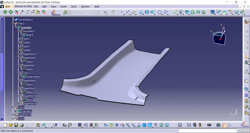
Drafting Analysis of the Final output:
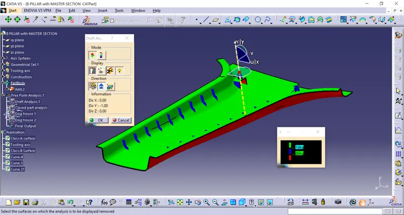
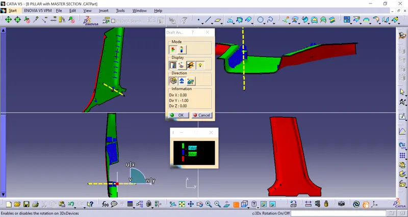
- After creating the solid body we will perform the draft analysis of the whole part body.
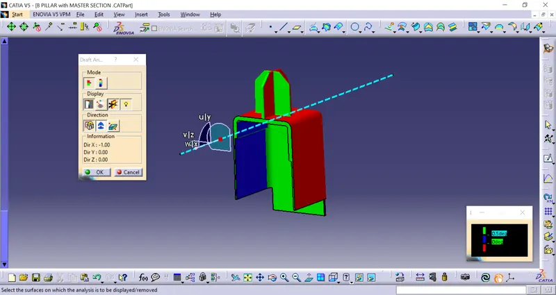
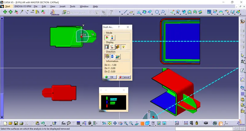
- First, change the parameter to material mode and then go to perform draft analysis Go to Insert > analysis > feature draft analysis.
- Click on the compass icon & align with the tooling axis.
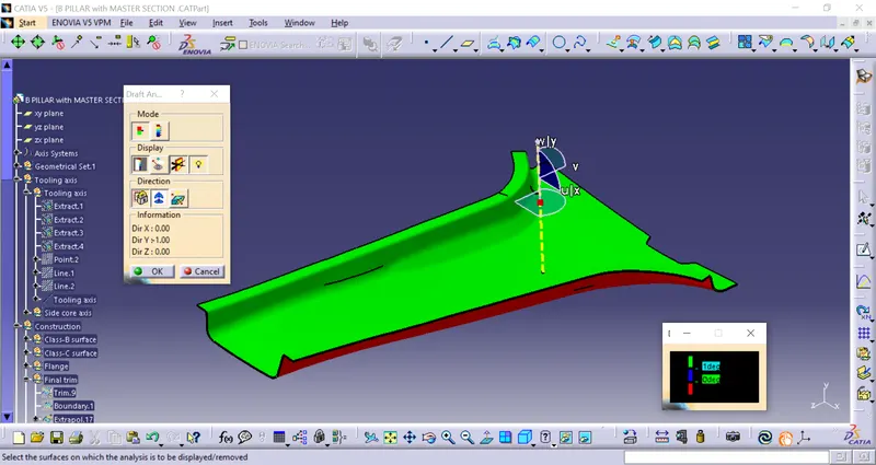
Creating a Dog house:
Extracting the Dog house boundary from curve-3 and extracting the line towards the plane.
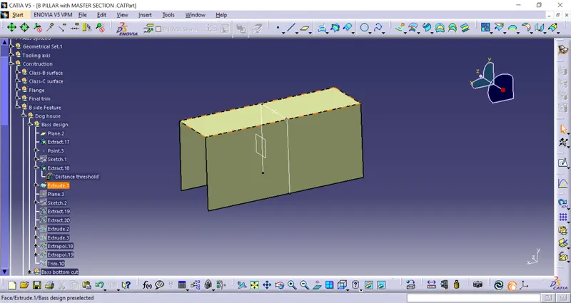
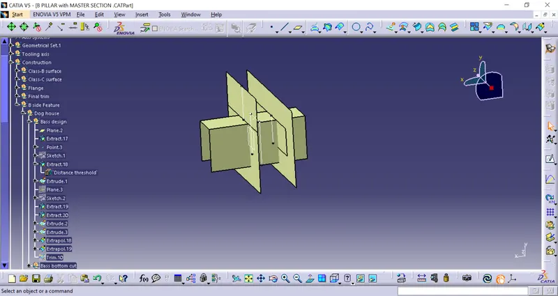
Extract the lines from Curve-4 and extrude the lines towards the y-direction.
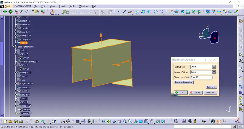
Thicken the extracted surface to form a solid dog house.
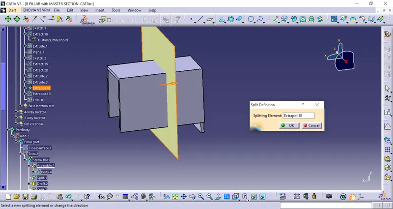
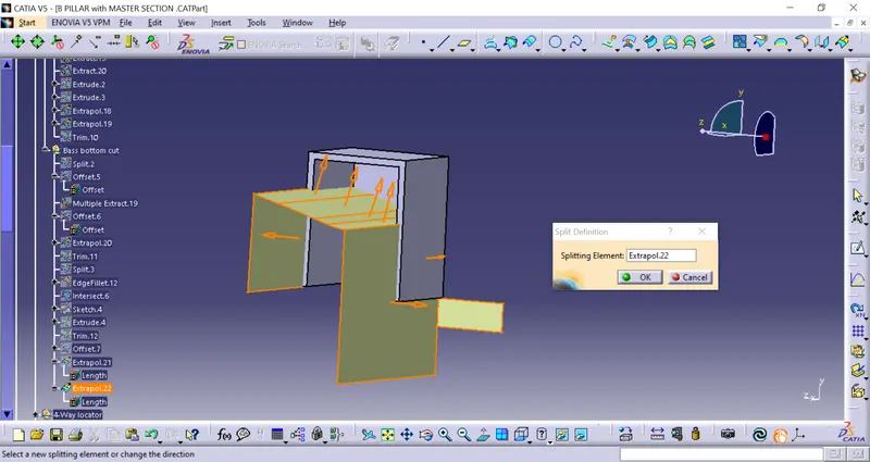
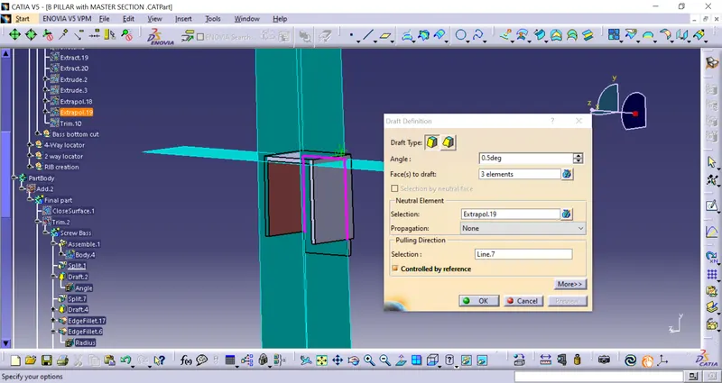
The draft should be at 0.5Degree
DESIGNING OF LOCATORS:
What are locators?
Locators work as The 3-2-1 principle of location (six-point location principle) is used to constrain the movement of the workpiece along the three axes XX, YY, and ZZ. This is achieved by providing six locating points. There is a total of 12 degrees of freedom, 6location, and 9 translation.
In this, I need to fix any 11 degrees of freedom permanently and anyone to be clamped or fixed temporarily.
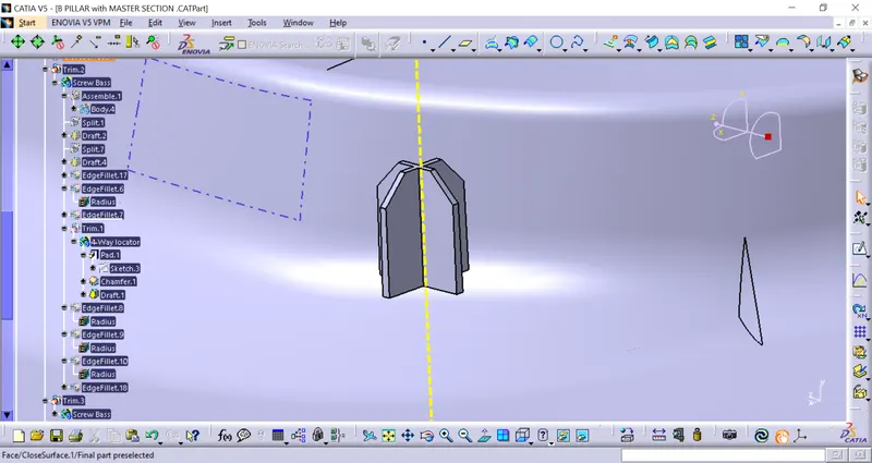
4-Way locators
Taking the reference From Curve-3 And 4.
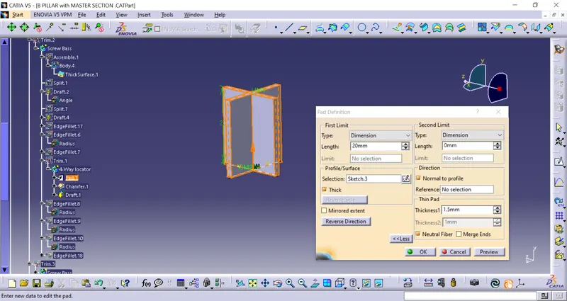
Thick the line from pad commends for 0.8mm(40% wall thickness of 0.4*2mm)
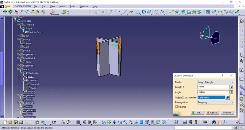
Chamfer the edges around 45*5mm
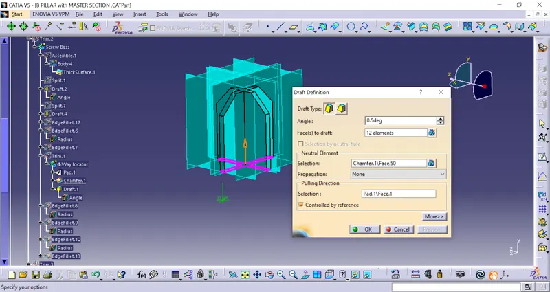
Drafting every face around 0.5Degree
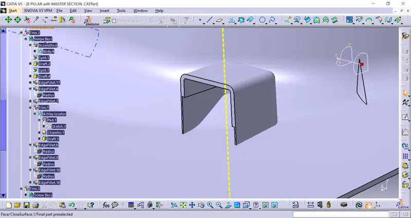
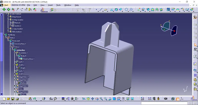
Add the locator to the Dog house using Boolegen untrim.
Drafting Analysis on dog house assembly:
DESIGNING OF RIB:
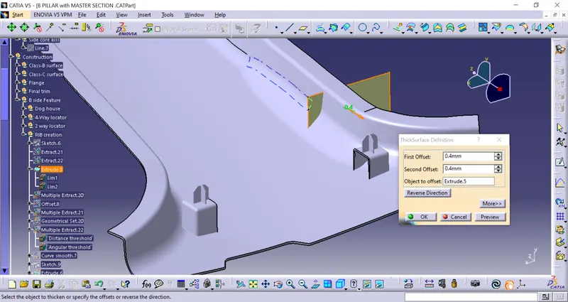
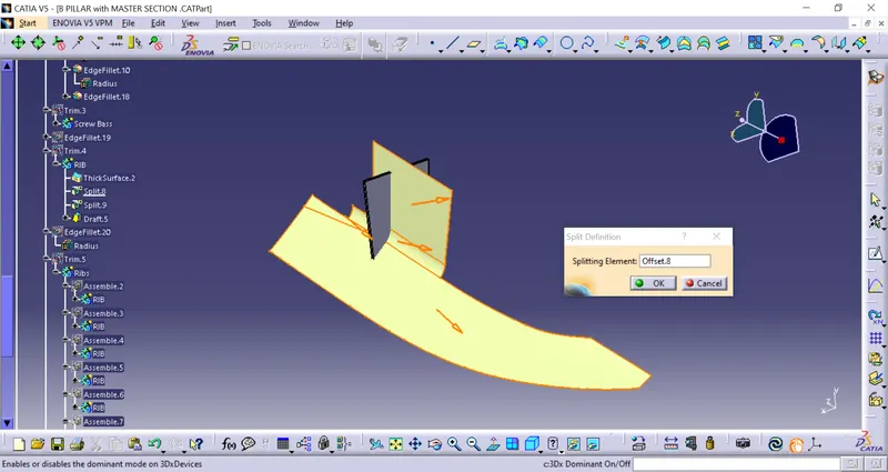
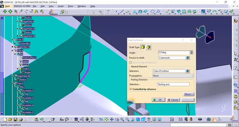
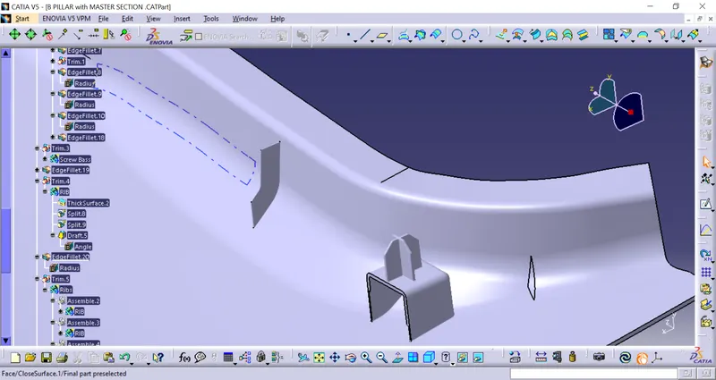
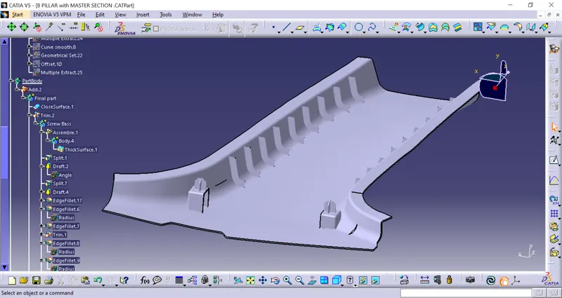
Creating the rib as per design rules given the draft angle and fillets.
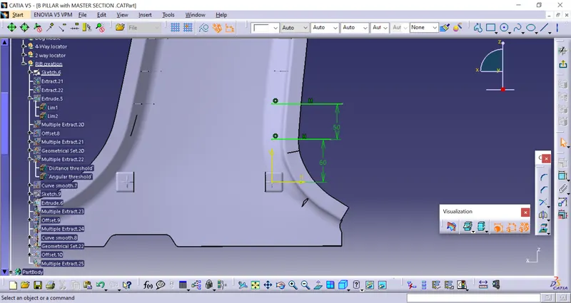
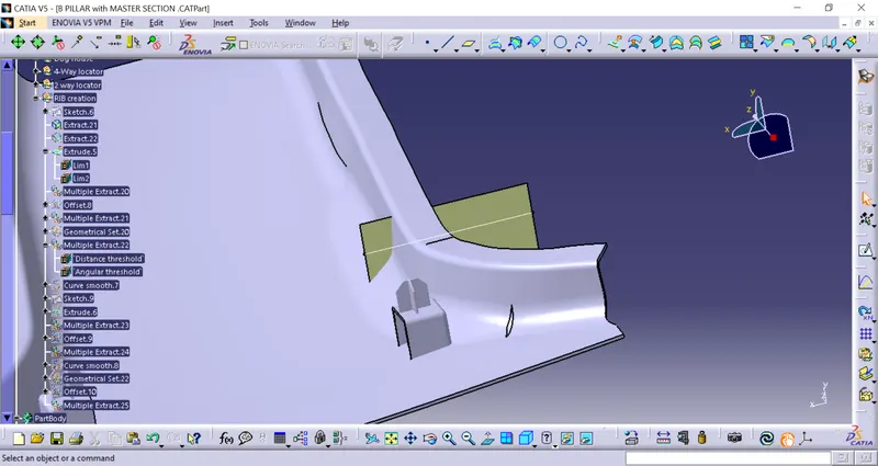
Thicken the surface by 0.8mm as rib
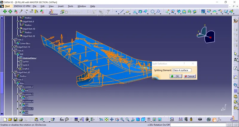
Drafting analysis on B-piller:
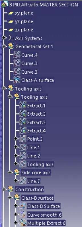
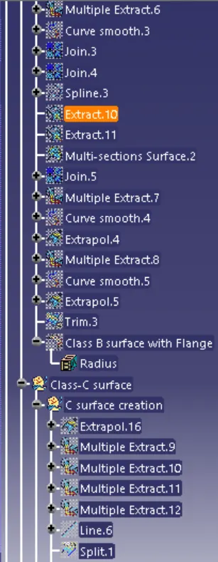
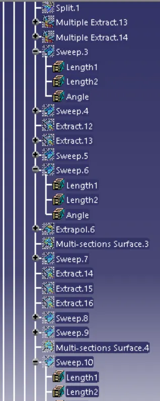
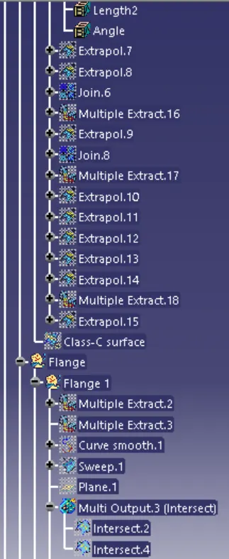
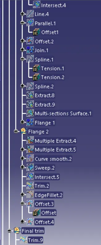
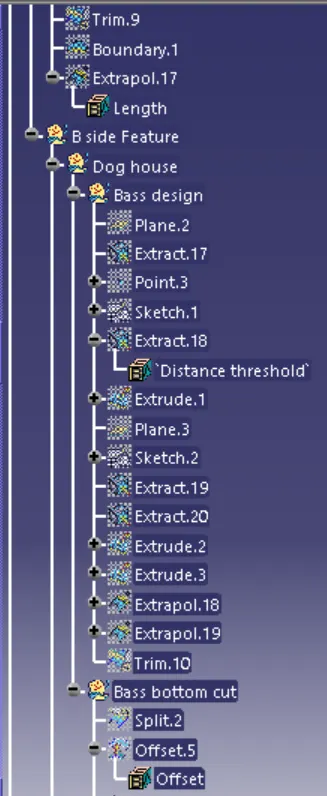
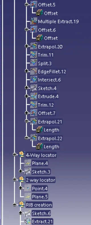
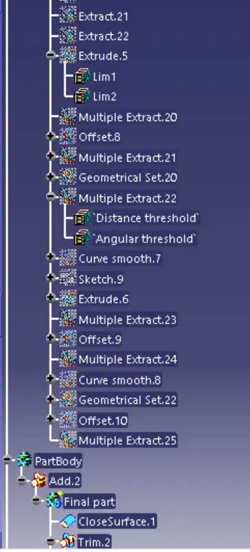
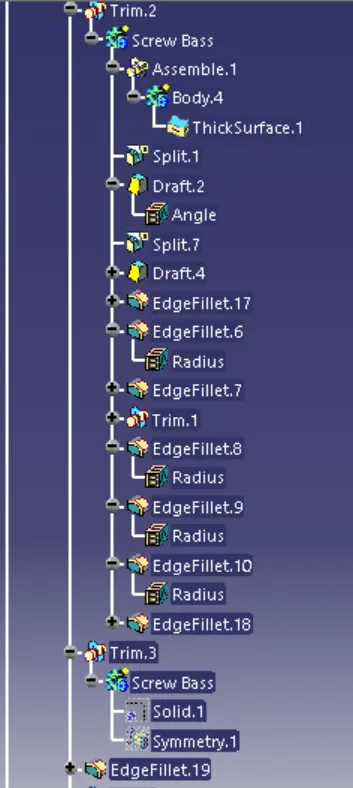
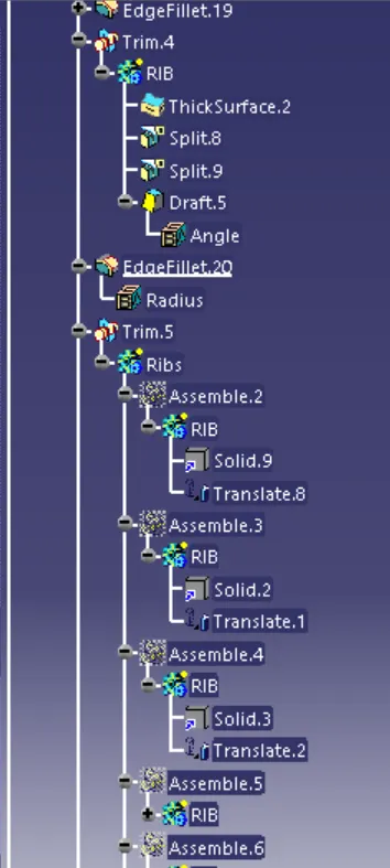
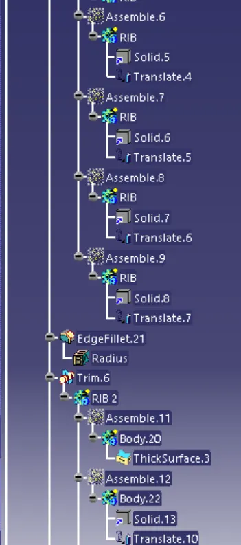
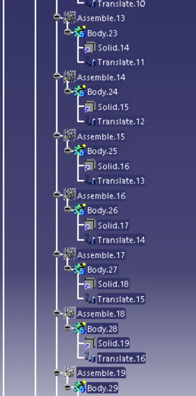
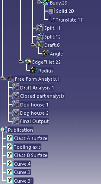
Tree structure: