Week 9 - Project - Master Section Development
Project - Master Section Development.
Aim:- To create the Solid body Using Closed Body Command of B Piller From the Given Class A Surface and Create of Engineering Feature.
Objective:-
- To create Class B surface & Class C surface From Given Class A surface.
- To make Closed Body Using closed body command.
- Create tooling axis for B piller Body name as main tooling axis and side tooling axis.
- To develop attachment feature for fixation of part by follwing OEM Design standard.
Theory:-
Class-A Surface:- is a term used in specifically in automotive design. It describes the final production surface data for the aesthetic parts of the car. This is because as it achieves the highest surface quality levels, and it demands a high level of automotive design knowledge as well as surface modeling skills.
Class B Surface :- This surface is created by taking offset from class A Surface.It is surface which all engineering features like Screw bosses,dog house, rib and mounting are created.
Class C Surface:- This is Surface which joined the Class A Surface and Class B Surface.
Tooling Axis:- It is the direction in which Core and Cavity open and closed.
Draft Analysis:-
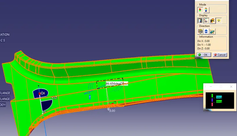
The Draft Analysis command enables you to detect if the part you drafted will be easily removed. This type of analysis is performed based on color ranges identifying zones on the analyzed element where the deviation from the draft direction at any point, corresponds to specified values. All plastic components will have a minimum draft of 0.5 to 3 deg for automotive sheet metal parts the draft will be 7 deg or more.
Observe the Color range:-
- Green - Draft value above 3 degree
- Red - Draft Value below 0 degree
- Blue - 0 To 3 dregree
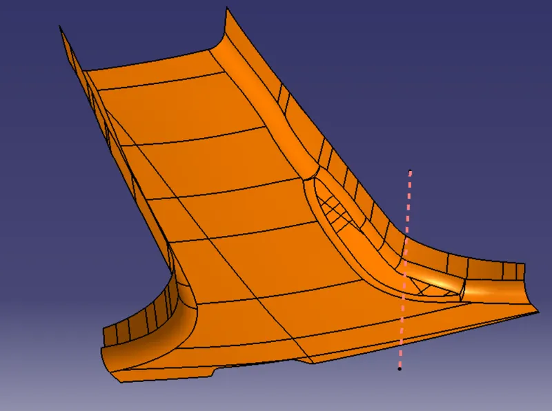
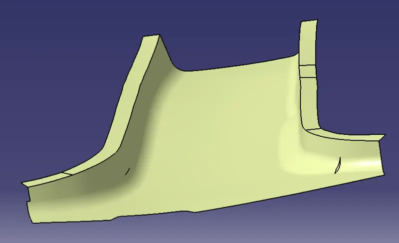
Given Class A Surface:-
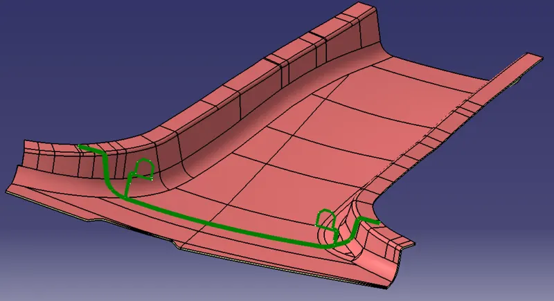
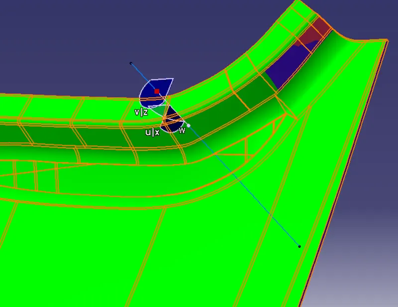
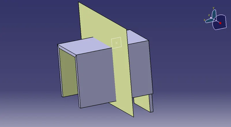
B Piller With Master Section
Procedure:-
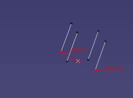
Tooling Axis Creation:-
- We have Creating tooling axis by Extracting master section line and taking the point middle and tooling axis created using bisecting method.I Have give name as main tooling axis.
Draft Analysis for Class A Surface:-
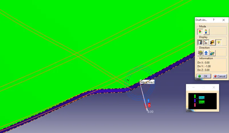
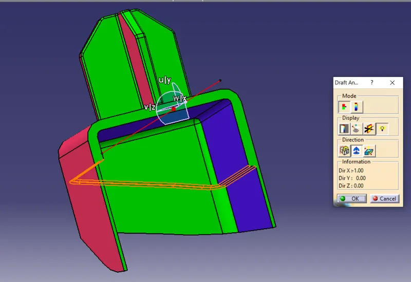
- Select the draft tool analysis and change the material mode.
- Drag the compass red point on Tooling axis
- Adjust the draft direction to moulding axis using the compass.
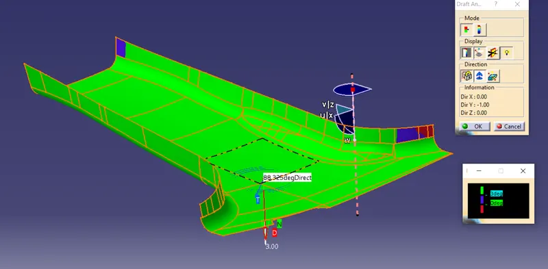
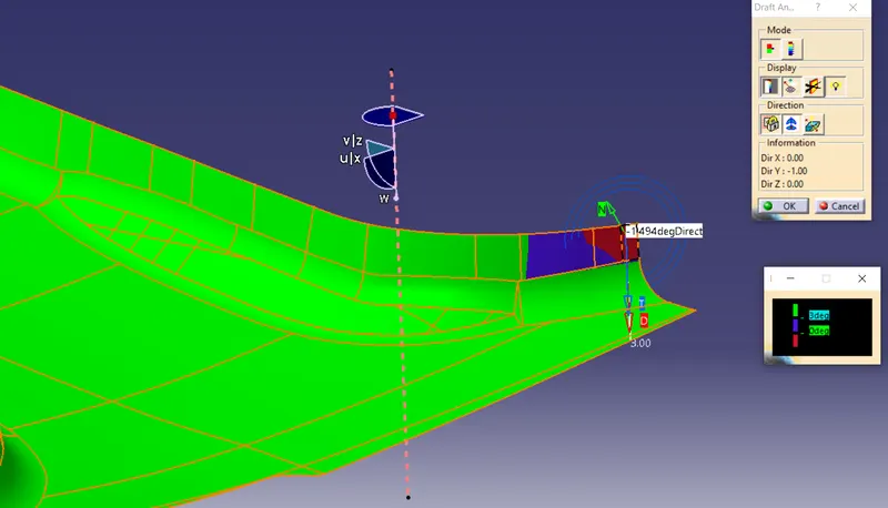
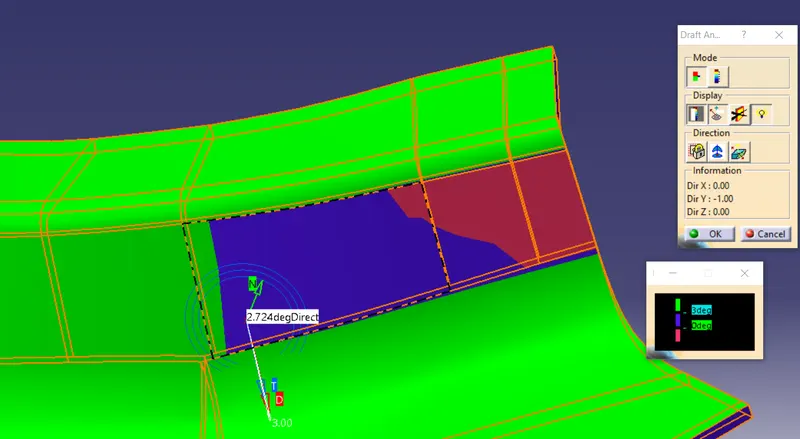
We have draft analysis on given Class A Surface the Green color show draft angle above 3 degree. we see right side small patches created and show color blue the angle between 0 to 3 Degree and red color show the angle below 0 degree.
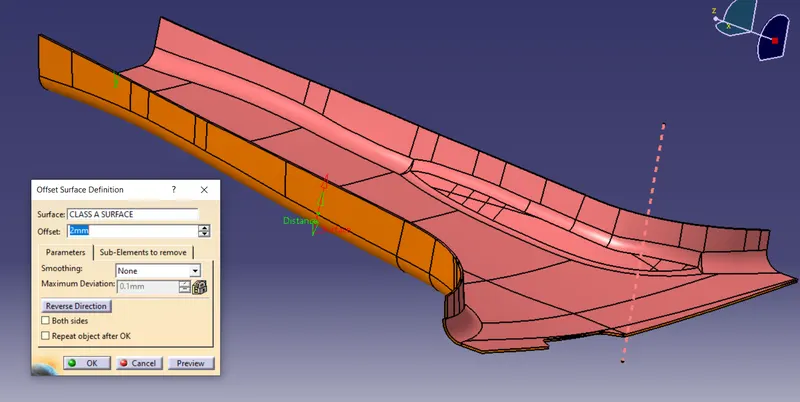
1. We have Offsect the Class A Surface Inward at 2mm. I have give name as Class B Surface.
2. Fistly Create a flange on Class A surface By referance of master section by using Sweep command on the the direction of main tooling Axis. Trim the class A flange and Filled the Edge of flange Using Edge Filled Command.
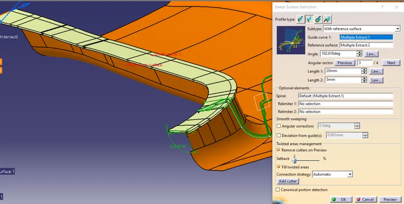
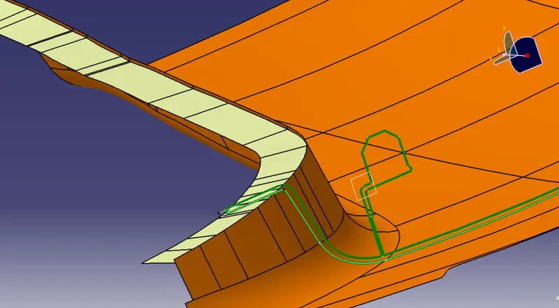
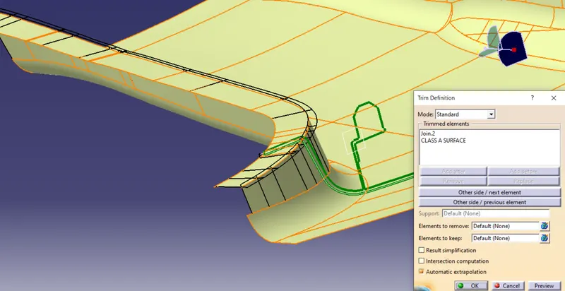
3. Second Create a flange on Class B surface By referance of master section by using Sweep command on the the direction of main tooling Axis. Trim the class B surfece flange and Filled the Edge of flange Using Edge Filled Command.
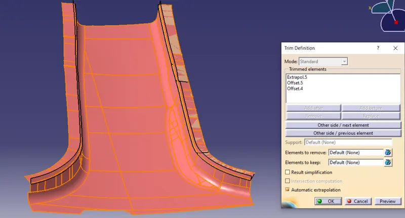
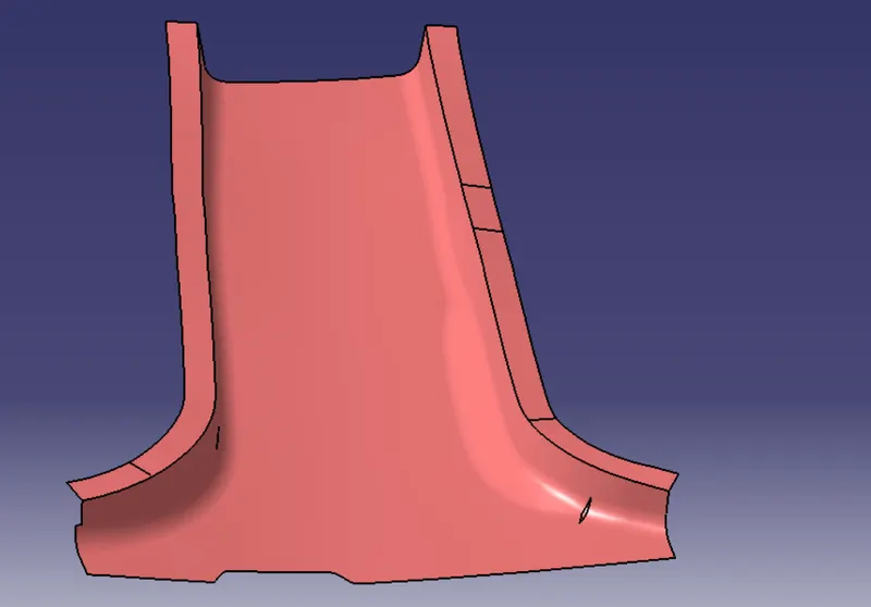
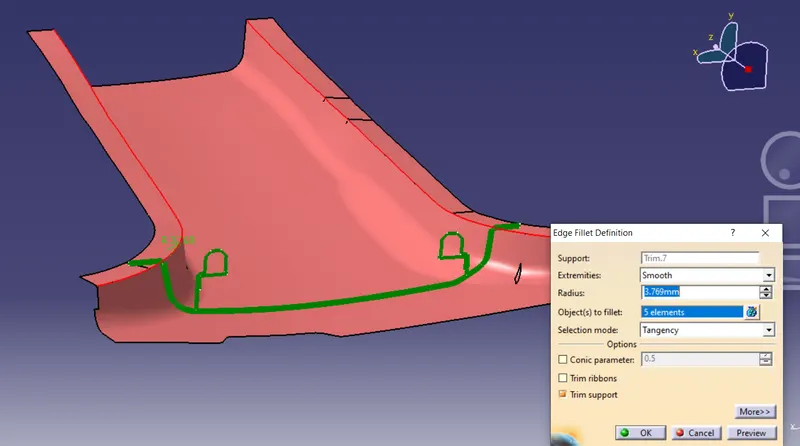
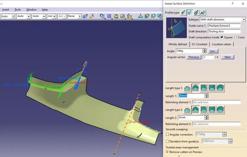
4. We have Create a Class C Surface by using Sweep command by subtype "With Draft Direction" on draft direction Toolinh Axis With Draft angle 3 deg.
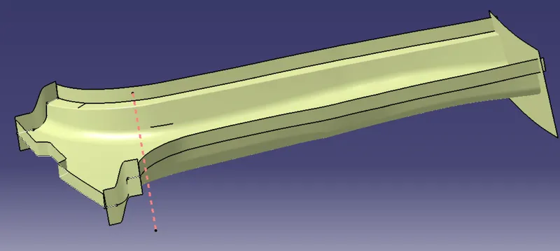
5. The Class A Surface of extra flanges Trim It.
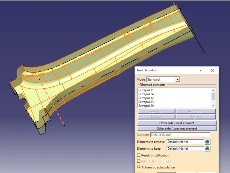
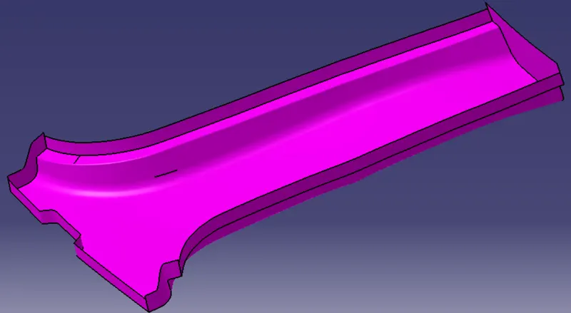
6. Trim the Class B suraface With Class C surafece. we have got Closed surface body.
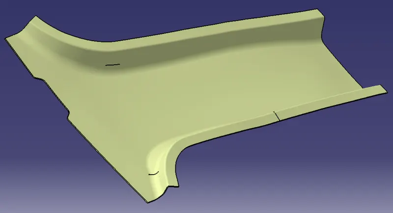
7. Create Solid Body using Closed body command.
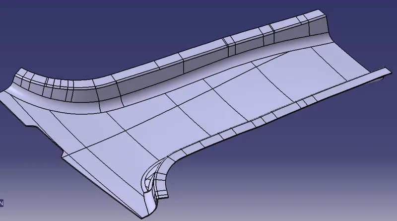
8. Draft analysis for on B Piller Solid Body.
Creation of Dog House:-
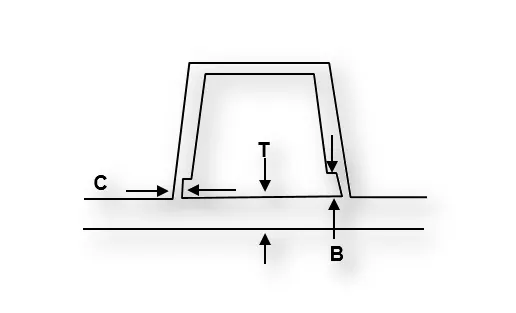
i) Doghouse wall thickness at the intersection of the part wall (C) should be 40% or less than the main wall stock (T).
ii) The Height of B should be between 3 to 6 mm.
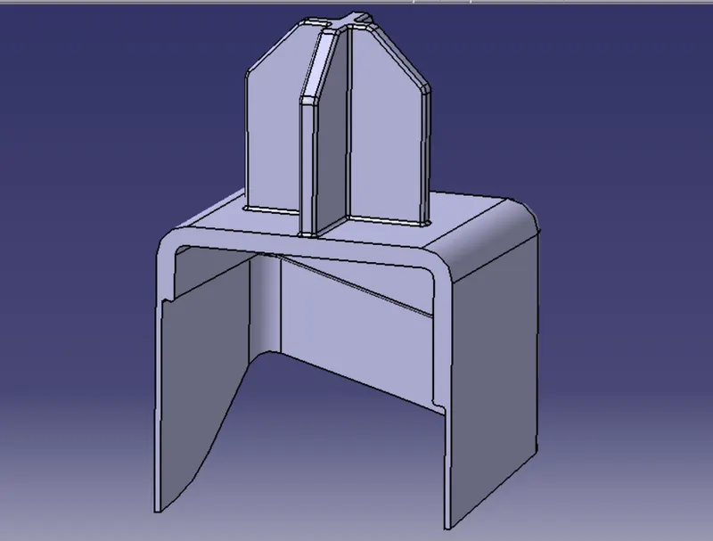
9. Create sketches for dog house and Extrude the sketches by referance of master section. Create thick body using thickness command.
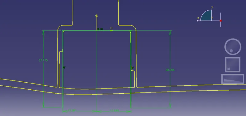
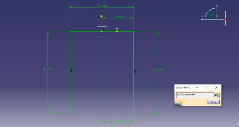
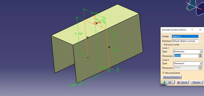
Draft Analysis For Dog House wrt Side core axis:-
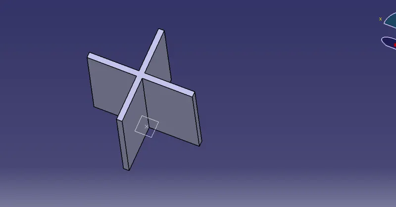
Creation of 4 Way Locator:-
4 Way locator mean you prevent movement at 2 axis (+X,-X,+Y,-Y) on the plane.
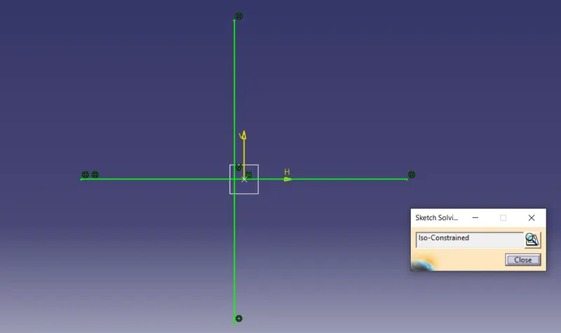
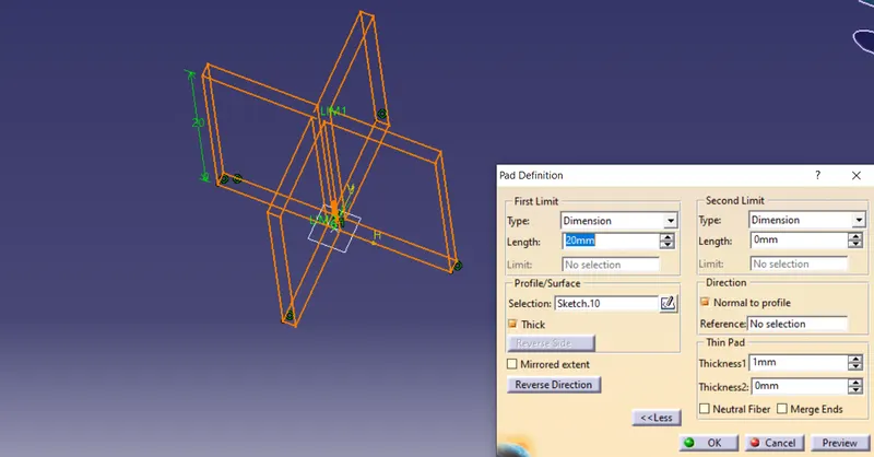
10. Create sketches for 4 way locator and Pad the sketches by referance of master section.
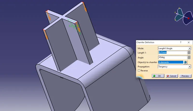
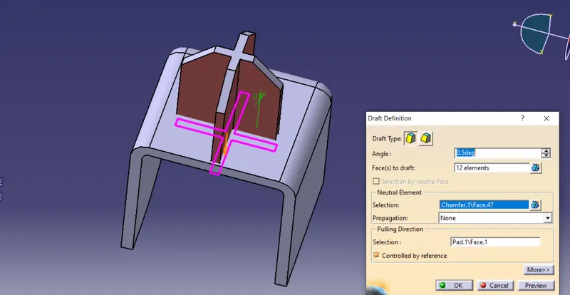
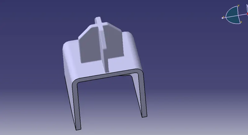
11. Now we do on 4 way locator apply chamfer, fillet and Darft operation.
Creation of Rib:-
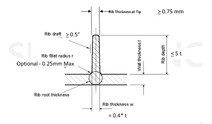
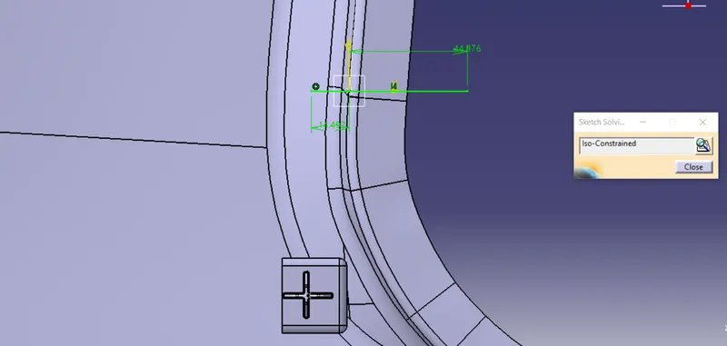
12. Create Sketche for Rib and a rib for 50mm around the surface.
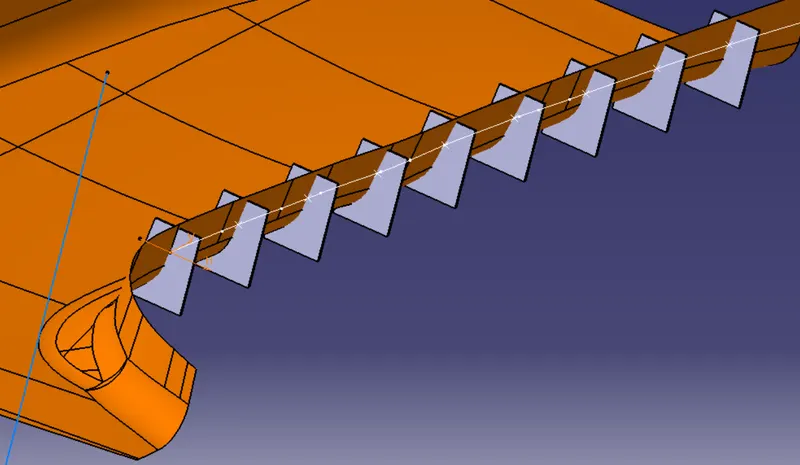
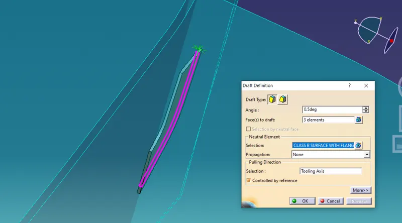
13. apply Draft angle on Rib.
3D Model:-
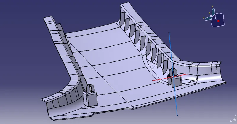
Draft Analysis Report on main tooling axis:-
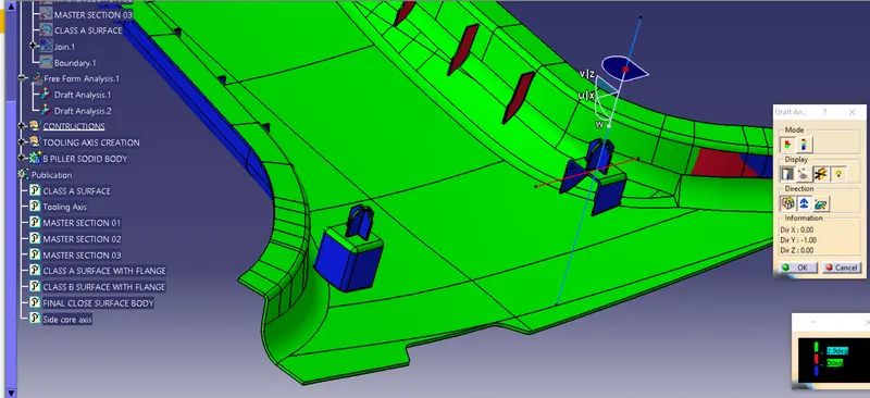
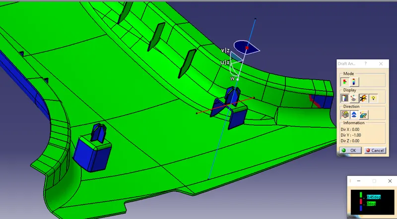
The faces Green color show draft angle above 3 degree.
blue the angle between 0 to 3 Degree and red color show the angle below 0 degree.
Draft Analysis Report on Side tooling axis:-
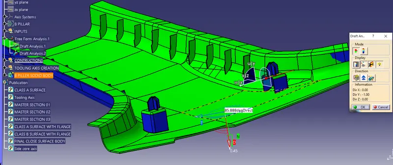
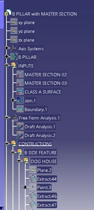
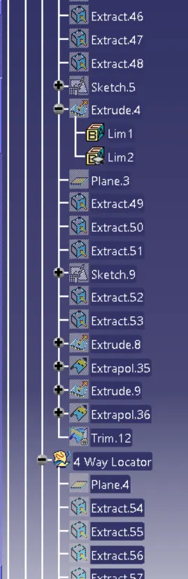
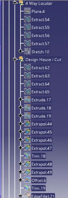
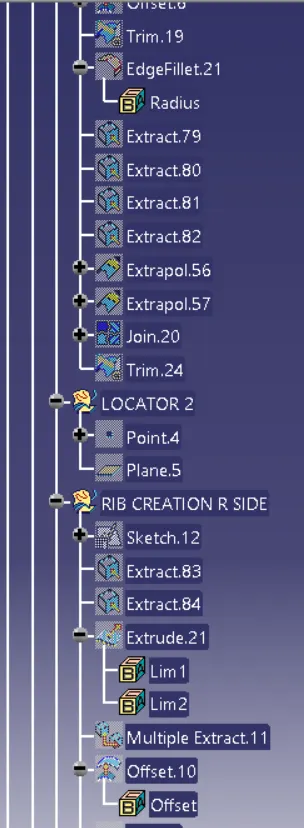
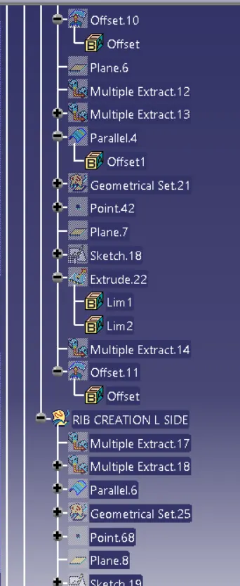
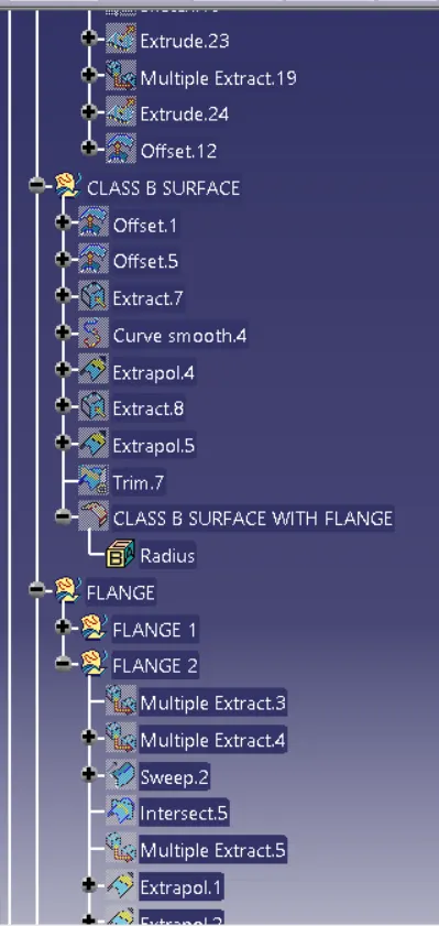
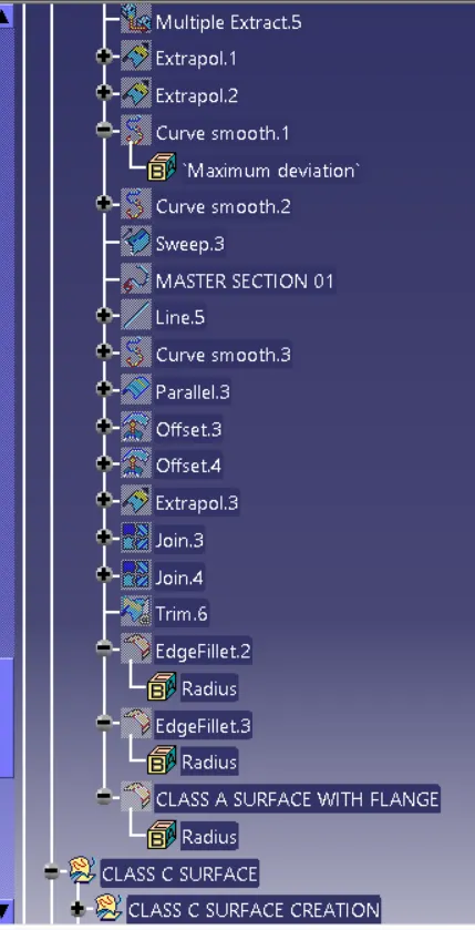
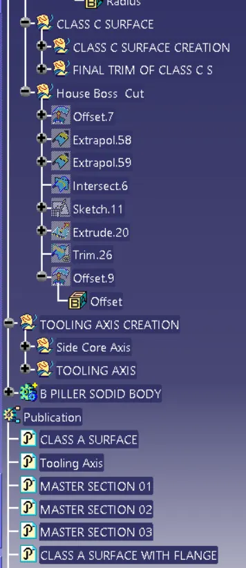
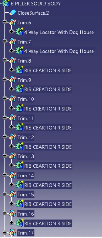
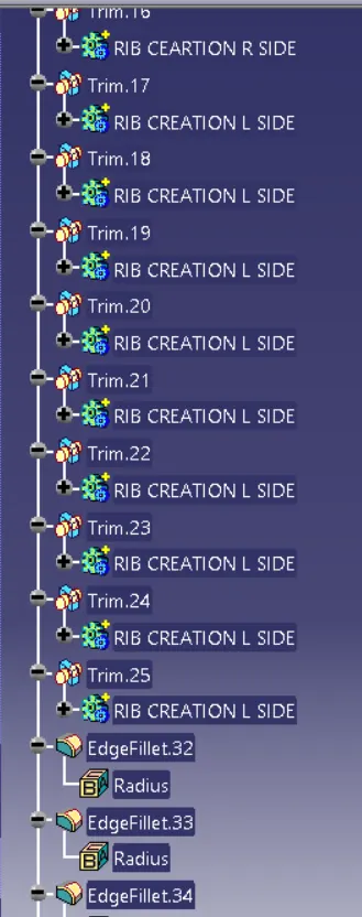
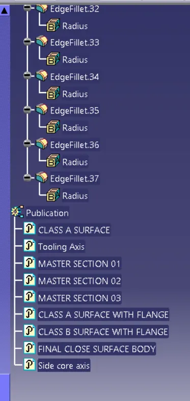
Tree Structure Of B Piller:-
Conclusion:-
- Created Class A, Class B, and Class C Surafce as per the automotive standard.
- To perform Draft Analysis on Final B Piller Model.