Week 9 - Project - Master Section Development
AIM:
The goal of the project is to use CATIA V5 software to generate a solid body of the B pillar from the input provided as the class A surface and connect attachment features for fixing the component at the proper position with the main component.
INTRODUCTION:
The B pillar is a component found between the front and rear doors of a car that connects the body to the roof.
The steps involved in creating the aforesaid project are listed below.
1. Importing the B pillar's class A surface.
2. Identifying the primary tooling axis for the component.
3. Creation of a class B surface for the B pillar
4. Creating a class C surface that sits between the class A and class B surfaces.
5. Forming a solid closed body from a closed surface
6. Attaching the dog house, locators, and ribs to the class B surface.
7. Determining the lifter axis for Dog house tooling.
Draft Analysis of the Class B Surface and the Dog House,
PROCEDURE:
Tooling Axis:
The given Class A input is analysed in order to visualise the item to be manufactured, and the tooling axis, also known as the tooling direction or die line, is the direction in which moulds pull apart in injection moulding. Core and Cavity are the names of two mould pieces. Thus, tooling direction determines mould separation and also plays an important role in the development of the plastic product, which is drafted to the desired nominal angle for possible clearance and ejection of the final part from the mould.
The Steps Followed In Creating Tooling Axis
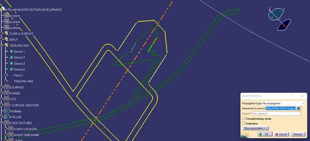
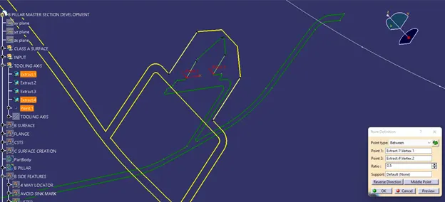
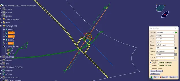
A Reference Point Is Created Along The Surface Zero And A New Axis System Is Created -The X And Y Directions Along Class A Were Used To Create Tooling Directions. Finally, by bisecting the two lines, the tooling axis is created and published. Class A Surface Is Used As Input Using Surface Operation Commands Class B Is Created.The Tooling Axis Determines The Class C Boundary Swept Direction With Draft Direction.
When seen from the tooling direction, all of the drafted parts should be visible, giving a rough idea of product manufacturing. There are two tooling directions in injection moulding in the B Pillar model. Because the attachment feature is bounded by close walls, one on the main tooling and the other on the lifter side are used to eject the parts during injection.
A Surface Improvement.
We Need To Check The Quality Of The Given A-Surface Before We Begin Making The Closed Body For The B-Pillar. The A-Surface Must Be Free Of All Patches Or Error Elements. To begin, we must disassemble the given styling surface and join it with a merging distance of 0.001mm.
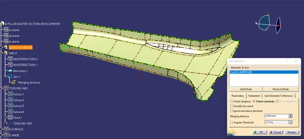
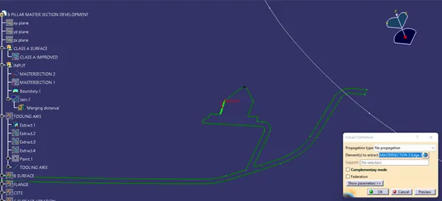
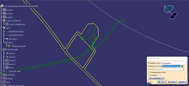
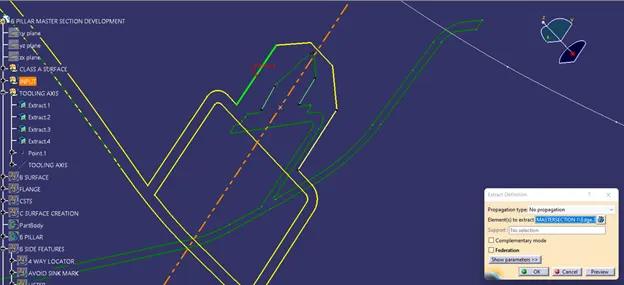
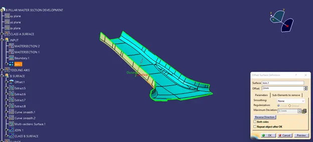
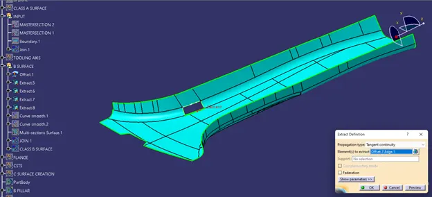
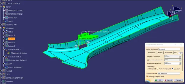
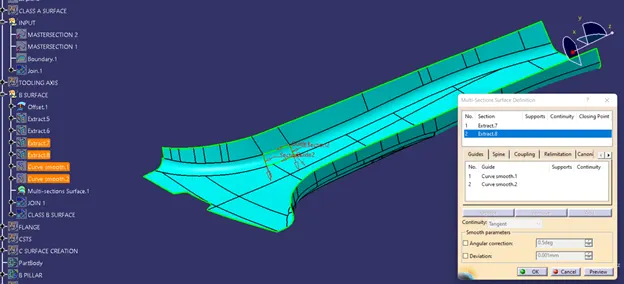
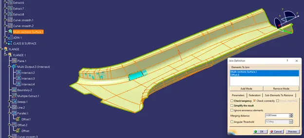
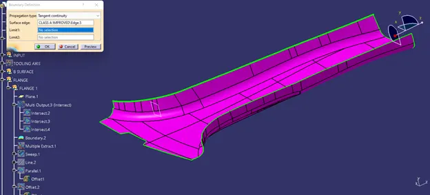
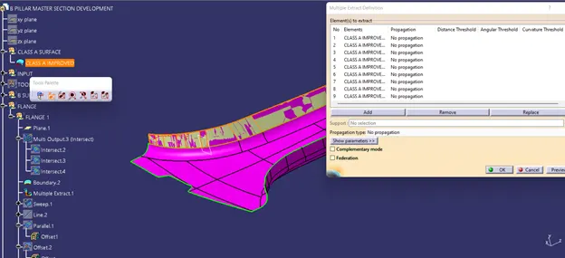
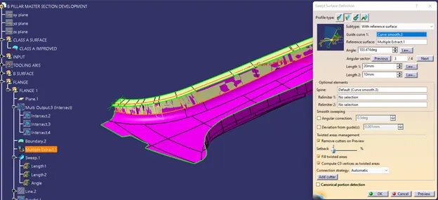
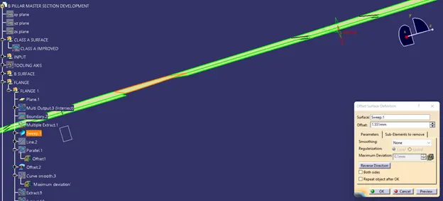
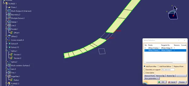
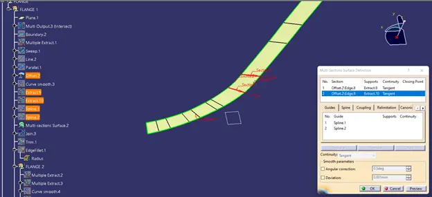
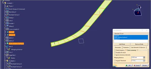
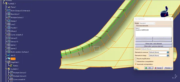
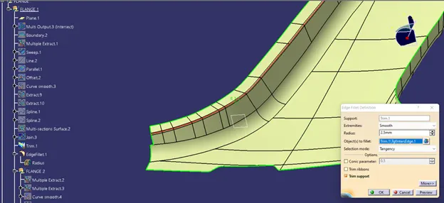
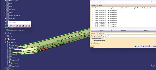
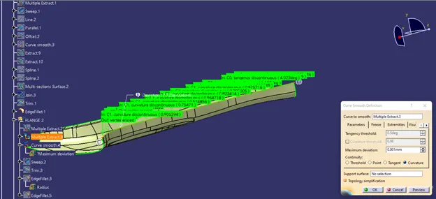
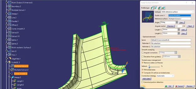
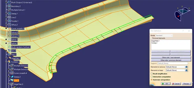
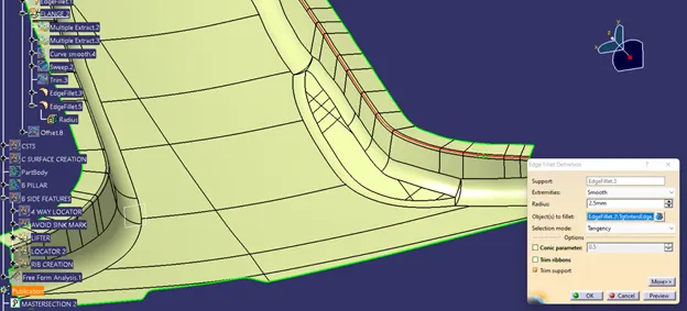
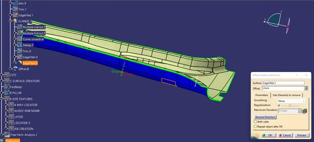
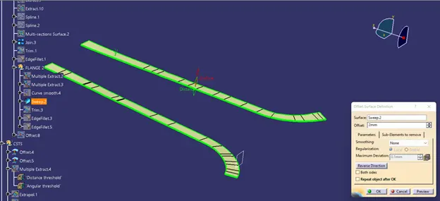
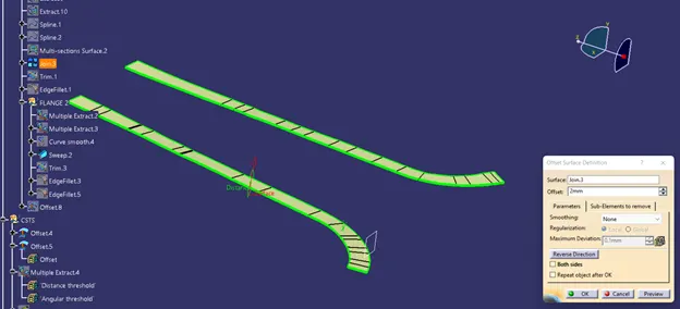
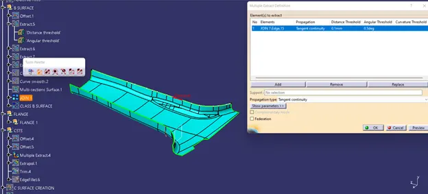
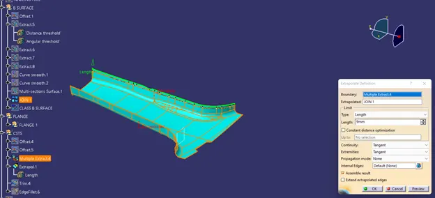
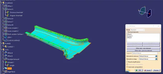
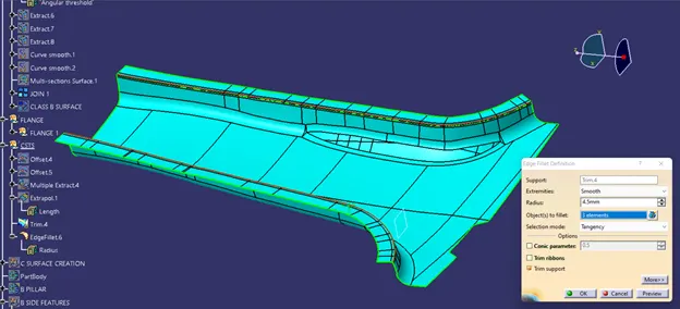
This is final class b surface.
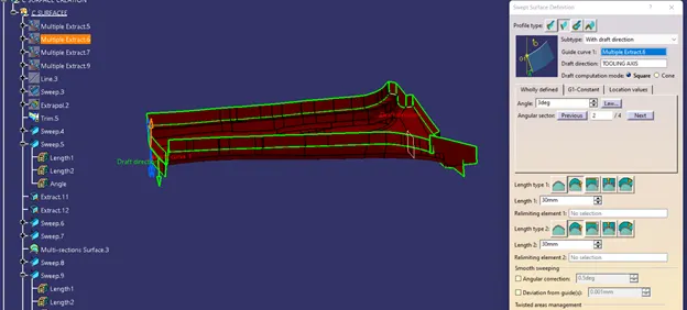
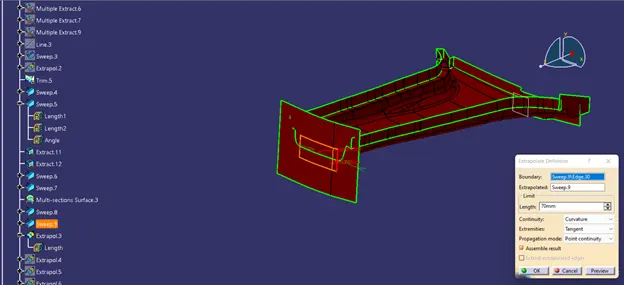
NOW EXTRACT ALL THE BOUNDARY
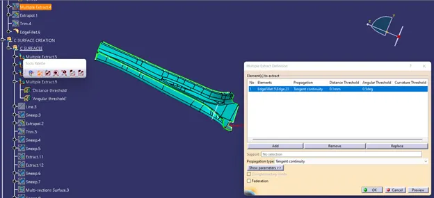
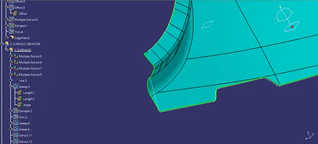
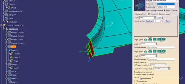
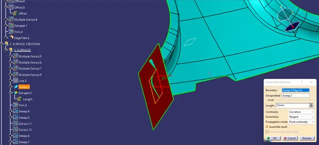
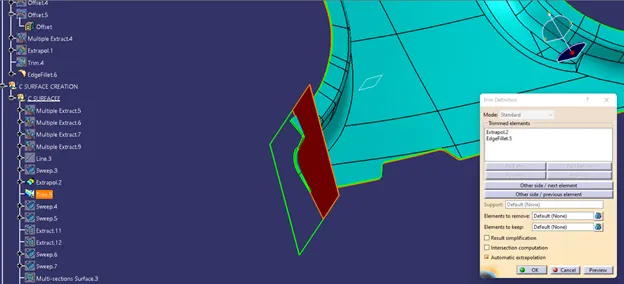
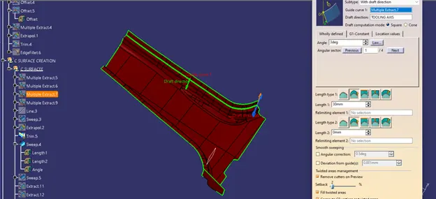
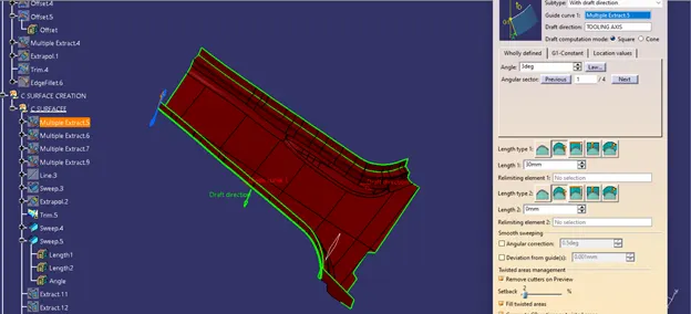
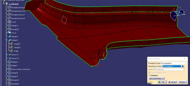
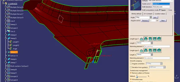
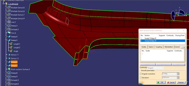
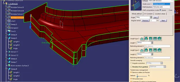
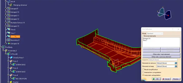
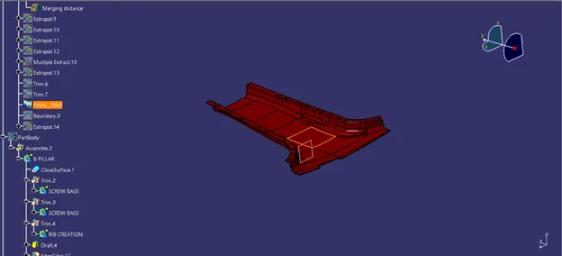
Now trim all the extrapolated surface.
Now creating 4-way locator.
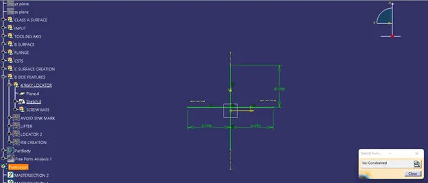
Now creating the screw bass
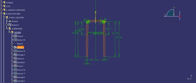
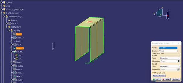
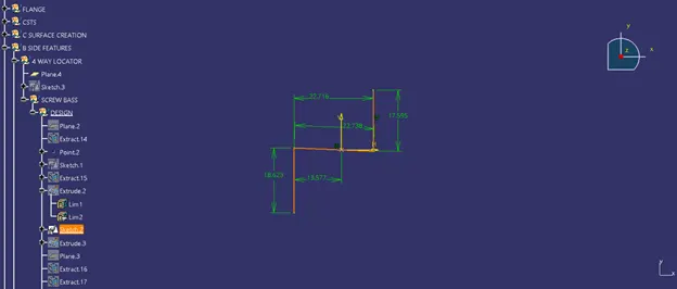
Extract the sketch as shown below.
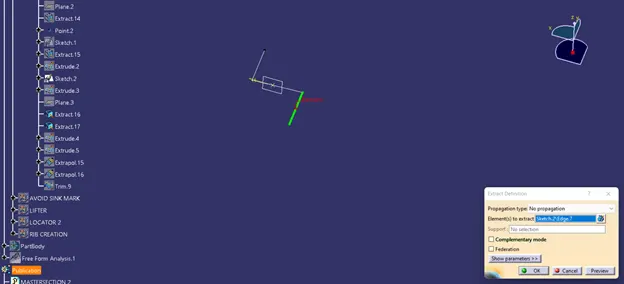
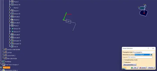
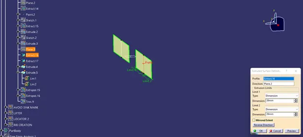
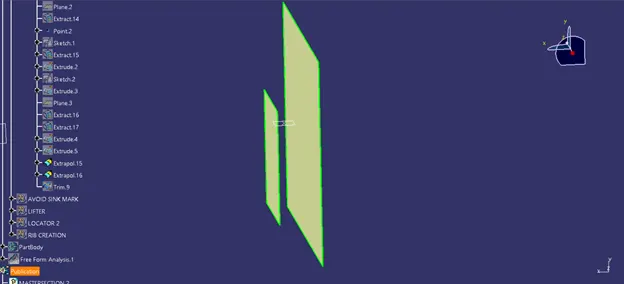
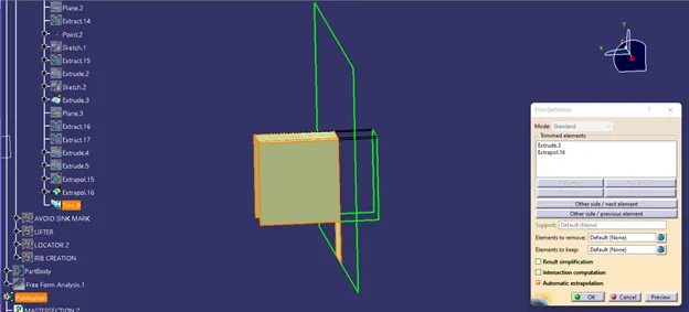
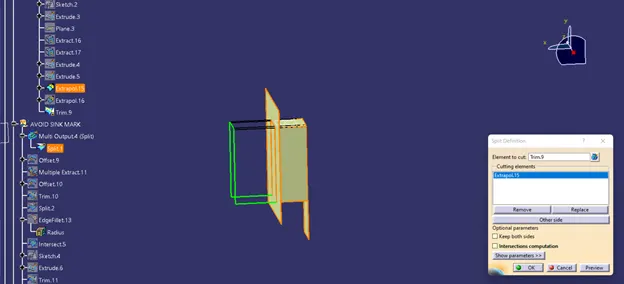
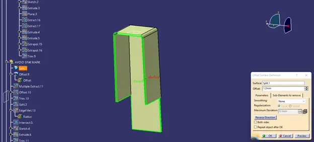
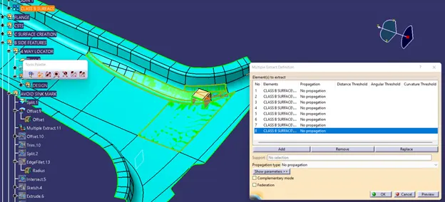
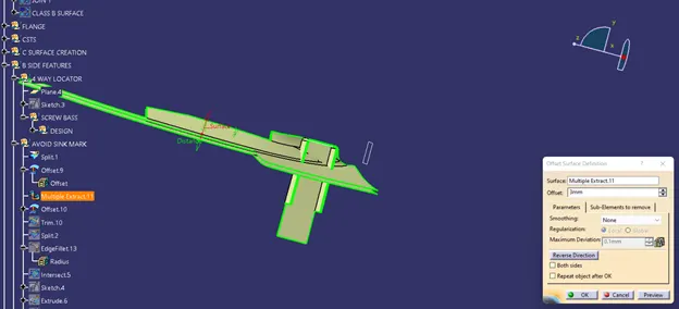
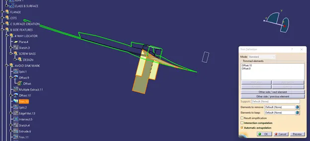
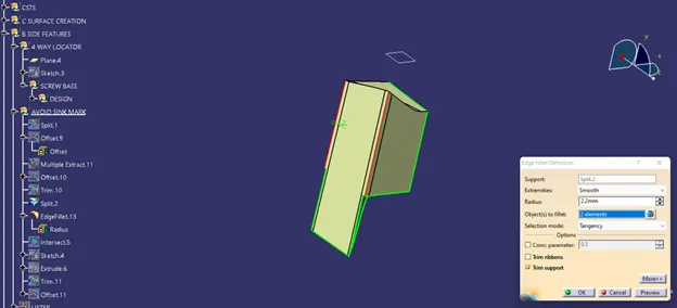
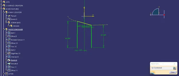
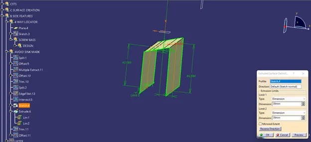
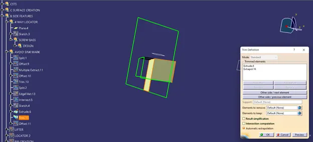
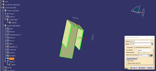
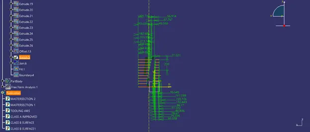
Extract the sketch
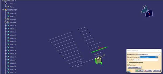
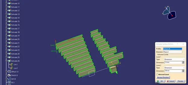
Now apply thick option and then split it.
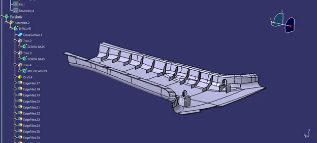
Now apply draft and then use edge fillet and then assemble it.
After applying draft analysis.
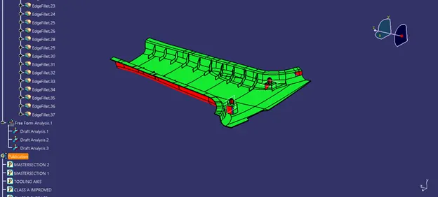
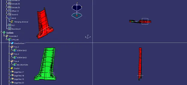
Isometric, top view, Side view.
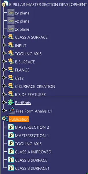
Geometrical sets
Conclusion:
B Pillar component with engineering features using the master section and styling surface as an input have been successfully created and
draft analysis have also been performed for the same.