Week -2
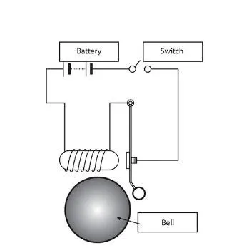
- Make a Simulink model of Doorbell using solenoid block with the following details:
In the above arrangement, when the switch is closed the electromagnet receives electrical power from the battery and pulls the metal arm to hit the bell producing sound.
Create a situation where the switch is closed for 2 seconds and then released. Observe the physical movement of the plunger.
Aim: -
To develop a Simulink model of a doorbell using a solenoid block to simulate a circumstance in which the switch is closed for two seconds and then released, as well as to monitor physical movement of the plunger.
Doorbell: -
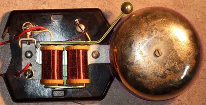
The doorbell operates on the electromagnetic concept. It makes use of a solenoid. When the switch is closed, electricity flows into the solenoid, creating an electromagnetic field. The plunger moves as a result of electromagnetic fields and makes a sound when it collides with a bell. Door knockers are low-voltage devices.
Electromagnet: -
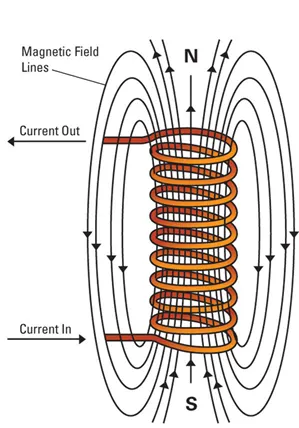
Electromagnets are non-permanent magnets that generate a magnetic field when an electric current is passed through a coil. When the flow of electricity is interrupted, the magnetic field vanishes. The primary benefit of an electromagnet versus a permanent magnet Is the magnetic field's ability to be swiftly adjusted. The magnetic field can have a wide variety of values by varying the strength of the electric current. In the case of electromagnets, however, a continuous supply of electrical energy is necessary to maintain the field.
Solenoid: -
A solenoid is a three-dimensional wire structure. When a wire is wound around a metallic block in a coil and electricity is delivered through it, it acquires some unique magnetic properties. Electromagnetic induction converts it into an electromagnet that can be turned on and off. Because a solenoid functions similarly to a bar magnet, it has a wide range of applications.
Simulink model explanation-
Simulink – PS converter: -
Before providing input to the circuit, the signal from the source is transformed into a physical signal.
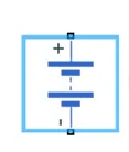
Battery source and Switch: -
A battery source is used to provide power, and a switch is used to control the open and closed circuits. If the switch's input exceeds the threshold, the switch will either close or remain open.
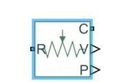
Ideal translation sensor: -
To track the plunger's moment, we'll need a sensor whose output is a physical signal.
Ps Simulink converter: -
It converts the Input Physical Signal to a Simulink output signal.
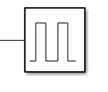
Pulse generator: -
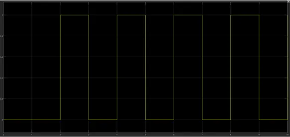
The pulse generator generates square wave pulses at regular intervals. The shape of the waveform is determined by the block waveform parameters, amplitude, pulse width, period, and phase delay.
Mechanical translation reference: -
This block is a mechanical translational reference point, such as a frame or a ground. It connects mechanical translational ports that are rigidly attached to the frame.

Scope: - It shows the signal that was generated during simulation.

Display: - It displays the outcome of the input data used to perform the simulation.
Electrical reference: -
A ground connection is essential in an electrical model.

Solver configuration: -
It defines solver settings to use for simulation.

Simulink model
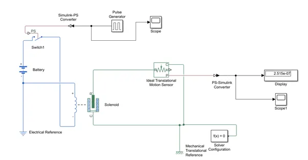
The switch block is controlled by an external physical signal, and if the external physical signal is larger than zero, the switch is closed; otherwise, the switch is open. The positive terminal is linked to the block, whereas the negative terminal is linked to the electrical references. We create a full electrical circuit by connecting the solenoid block to the switch and battery. The mechanical reference is linked to the common connection C. To monitor the movement of the plunger, the ideal translation sensor is linked to the solenoid block R. To obtain the output, the scope is linked to the ideal translation sensor. The pulse generator signal was converted using the Simulink Ps converter and sent into the input switch. A solenoid is installed, and a battery is attached to it. The voltage of the linked battery was set to be the same as the rated voltage of the solenoid. The switch is linked to the same circuit as well. An ideal translation motion sensor linked to the circuit measures the position of the solenoid plunger. The scope is linked in order to visualise its behaviour. To produce the required graph, the spring constant and damping value of the solenoid block were changed.
Input signals
Output signals: -
Conclusion for Door Bell: -
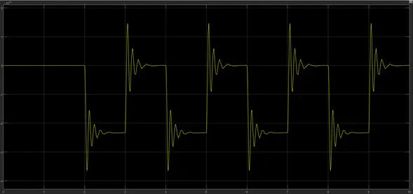
Giving the pulse generator input as a time interval of 2 seconds to open and close the switch. When the switch is closed, the solenoid, block, and plunger receive electricity from the battery and move from connection R to connection C, striking the bell and producing music. The physical movement of the plunger is detected using a translational motion sensor, and the physical output is transformed into a Simulink output model, which is presented in the scope. Vibration can be decreased by lowering the spring constant value and raising the damping value.
- Use a thermistor to sense the temperature of a heater & turn on or turn off the fan as per below conditions:
Temperature source: 20 °C from 0 to 10 seconds, 27 °C from 10 to 30 seconds, 23 °C from 30 to 50 seconds
Fan conditions: ON if the temperature above 25 °C, OFF otherwise
Aim: - Use a thermistor to sense the temperature of a heater and turn on or turn off the fan as per below conditions: -
- Temperature source: 20oc from 0 to 10 seconds, 27oC from 10 to 30 seconds, 23 °C from 30 to 50 seconds.
- Fan conditions: ON if the temperature above 25oC, OFF otherwise.
Objectives: -
- To generate a wave of temperature coefficient using suitable block.
- To obtain the characteristics curve for change in voltage w.r.t time.
- To control a DC motor for a given condition
Thermistor
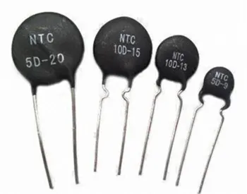
A thermistor is a resistance thermometer or a resistor with temperature-dependent resistance. The name is derived from the words thermal and resistor. It is constructed of metallic oxides that have been pressed into a bead, disc, or cylindrical shape before being encased with an impermeable material such as epoxy or glass. Thermistors are classified into two categories.
1) Positive Temperature Coefficient (PTC)
2) Negative Temperature Coefficient (NTC) (PTC).
When the temperature of an NTC thermistor rises, the resistance lowers. In contrast, as the temperature drops, resistance rises. This is the most common type of thermistor. A PTC thermistor operates in a slightly different manner. As the temperature rises, the resistance rises, and when the temperature falls, the resistance falls. This thermistor is commonly used as a fuse. A thermistor typically achieves great precision within a narrow temperature range of roughly 50oC around the desired temperature. This range is affected by the base resistance.
Blocks used: -
Simulink – PS converter: -
The signal coming from the source is converted into physical signal before giving the input to the circuit.
Thermal and electrical reference: -
These provides the reference point to the respective signals.

Scope: -
To view to characteristics of a property with the respect to time.
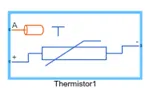
Thermistor: -
It is a resistance thermometer or a resistor whose resistance is dependent on temperature.
Resistor: -
The voltage- current (V-I) relationship for a linear resistor is V=I*R where R is the constant resistance in ohms.
Voltage Sensor: -
The block represents an ideal voltage sensor that is a device that converts voltage measured between an electrical connection into a physical signal proportional to the voltage.

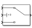
Switch: -
Pass through input 1 when input 2 is satisfies
Voltage controlled source: -
The block depicts a perfect voltage source, capable of maintaining the set voltage at its output independent of the current flowing through it.
Controlled Temperature Source: -
The Controlled Temperature source represents an ideal thermal energy source that is powerful enough to sustain the required temperature differential across the source independent of the heat flow absorbed by the system. Thermal saving ports A and B correspond to the source inlet and output, respectively. Port S is a physical signal port that receives the control signal that drives the source.

Explanation of model: -
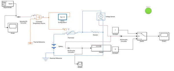
Inputs are sent into the Signal Builder, which is then linked to a Temperature Controlled Source in order to maintain the required temperature differential across the source. The input temperature is then sent through the thermistor.
Thermistor is connected to resistor to ensure that the thermistor is connected to the positive terminal of the resistor and that the voltage across the resistor is given by V (+) -V (-) and that the sign of the current is positive when flowing through the device from the positive to the negative terminal. This rule assures that a resistor's absorbed power is always positive. To obtain the values from the Voltage sensor, connect the positive terminals of the Voltage sensor and the Resistor. Switch is attached to the voltage sensor's output terminal. Using the Switch Parameter, indicate that the fan must be turned on if the temperature exceeds 25oC and off otherwise. Output is successfully executed by connecting with scope in accordance with the specified criteria.
Output: -
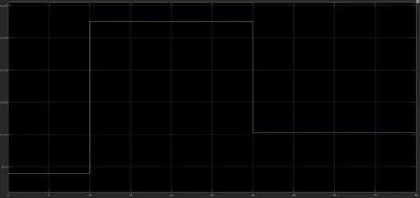
The curve shows the changes in the voltage as the condition is mentioned.
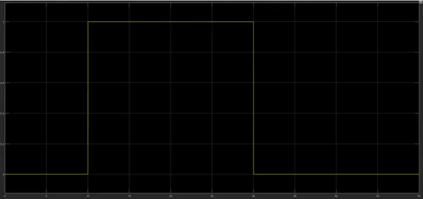
This clearly illustrates that from 0 to 10 seconds, the fan is turned off since the temperature is 293 degrees Celsius, which is less than 298 degrees Celsius. After 10 seconds, the temperature rises to 300 degrees Celsius, causing the fan to activate since the temperature surpasses 298 degrees Celsius. The fan was turned off after 30 seconds because the temperature had dropped to 296 degrees Celsius.
Conclusion: -
Hence the given conditions are satisfied using repeating sequence stair and switch block.