Week 8 - Challenge 1 - Draft Analysis on a Fan Cover
CREATION OF TOOLING AXIS AND DRAFT ANALYSIS FOR FAN COVER
Objective:
The main goal of this project is to use Catia V5 to develop the tooling axis and draft analysis for the fan cover.
Introduction:
The tooling axis is critical for the component to be created; if that tooling axis is used as a reference, the item may be manufactured without delay and will make the process easier. The drafting analysis will indicate the body's vital angles; it's critical to maintain a great draft angle.
Draft Analysis:
You can use the Draft Analysis command to see if the part you drafted can be readily eliminated. This method of analysis uses colour ranges to highlight zones on the investigated element where deviations from the draught direction at any point correspond to certain values.
The moulded components must eject from the die during the moulding process, and there are certain concerns with this, such as the moulded parts becoming stuck to the die or being damaged while being removed, thus we must set up the draught angle. This draught angle makes it easier for the moulded parts to expel from the die. The OEM standard for plastic component draught angles is 3 degrees, while the standard for sheet metal component draught angles is 7 degrees. This draught is evaluated to ensure the part has suitable draught angles.
Methodology/approach:
The class A surface is the first crucial input for creating tooling axes and draught analysis in Catia V5. Then, initially, create the tooling axis and draught analysis in Catia V5. Axis system for inserting.

Examine the best directions (X, Y, Z) and choose the one that is the easiest to produce. The Tooling axis is set to the Z direction; make an intersection curve in the ZX plane to see if any curves have different angles; if so, draw a bisecting line to retrieve the centre axis for both curves.
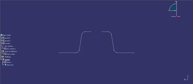
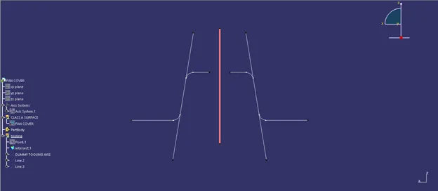
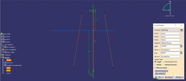
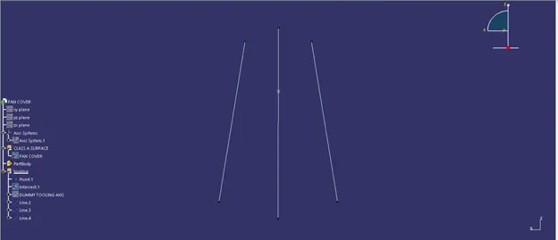
To find the mid axis, the same procedure is used in the ZY plane, which is to create an intersection curve and bisect both curves.
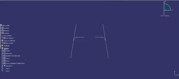
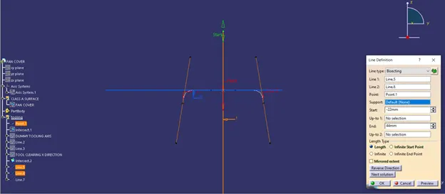
Then, utilising both axis from the two bisectors, bisect them again in the Z direction to produce the final tooling axis.
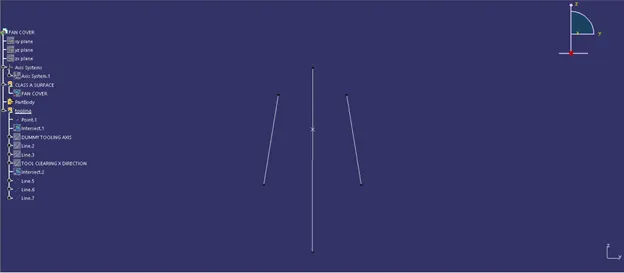
To acquire the draft analysis of the part, use the publish option to publish the Fan cover and the tooling axis.
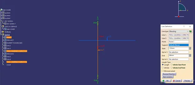
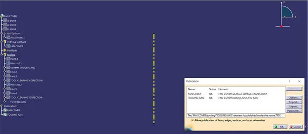
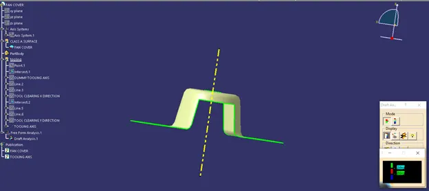
Use the analysis>Feature draft analysis toolbar to check the draft analysis, Use the compass and place in the Z direction line being upwards and lock it.
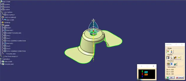
Select the axis and the part so that the color changes according keeping the reference as tooling axis.
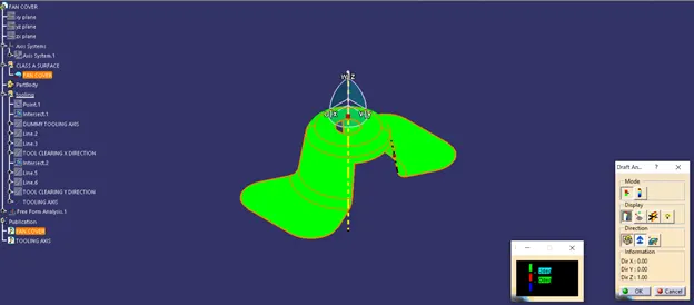
On the quick analysis mode there are 3 colors green, red and blue. We can change the values as per our standards, it is good to main standard drafting angles O to 3 degrees
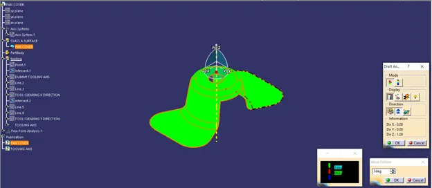
Analysis on running point - with the help of this option, the angles at every point can be checked easily.
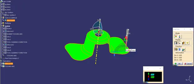
The draft analysis is completed for the for the class A surface.
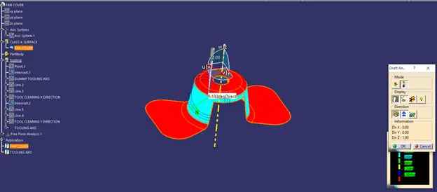
Change the view to the colour mode which allows us to see the different angles.
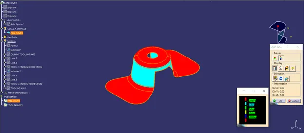
Isometric view
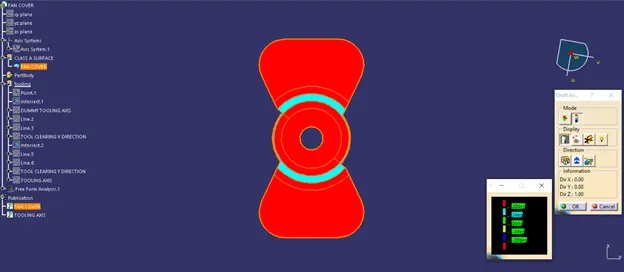
Top view
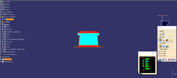
Front view