Week 8 - Challenge 2 - Base Bracket Design
Objective:
- For the supplied Base bracket model, create a B-class surface, a C-class surface, and a tooling axis.
- To publish the tooling axis, the class-A surface, the B-class surface, and the C-class surface.
- Conducting a draught analysis to ensure that the Tooling axis was created correctly.
Introduction:
CATIA V5
Dassault Systems developed CATIA, a multi-platform 3D software suite that includes CAD, CAM, and CAE. Dassault is a French engineering behemoth that specialises in aviation and 3D design. Product lifecycle management (PLM) software with 3D digital mock-ups CATIA is a solid modelling software that combines 3D parametric capabilities with 2D tools, as well as covering the entire design-to-manufacturing process.
CATIA may generate orthographic, section, auxiliary, isometric, or detailed 2D drawing views in addition to solid models and assemblies. In the drawing views, you may also generate model dimensions and create reference dimensions. CATIA's bi-directional associative attribute ensures that changes to the model are reflected in the drawing views and vice versa.
Generative Shape Design
It comes with a comprehensive collection of tools for building and changing mechanical surfaces that are utilised in the creation of complex shapes and hybrid parts. Its feature-based approach enables designers to capture and reuse design techniques and specifications in a productive and natural manner. Assist in the creation of sophisticated shapes based on a combination of wireframe and numerous surfaces. It has high-level capabilities, such as full specification capture and reuse.
A-Class Surface
A-Class surface is a word used in the design of plastic products. That is the smooth(aesthetic) or visible side of a component to the human eye after it has been built. It refers to those surfaces that are visible and adhere to the physical meaning of a product.
B-Class Surface
B-Class surfaces include the inside of your glove box, ashtray, and other auxiliary surfaces that you may view but are not as critical. These must also be smooth and "error-free," but they are not subject to the same high requirements as class A surfaces. It can also refer to a part's thickness.
C-Class Surface
C-class surfaces are backside surfaces that can contain tool marks, flash, and other flaws without affecting appearance, function, or other factors. It also refers to the combination of A and B to produce the C surface.
Draft Analysis
You can use the Draft Analysis command to see if the part you drafted can be readily eliminated. This method of analysis uses colour ranges to highlight zones on the investigated element where deviations from the draught direction at any point correspond to certain values. Molded portions must eject from the die during the moulding process, so there may be some challenges with removing the moulded parts if the die becomes sticky. Alternatively while removing the possibility of being injured, we must first set up the draught angle. This draught angle makes it easier for the moulded parts to expel from the die. If the component is made of plastic, the draught angle should be 3 degrees, and if it is made of sheet metal, the draught angle should be 7 degrees. This draught is examined to ensure that the part has suitable draught angles. OEM Features Draft Analysis Rules The truth is that there is no unique draught angle that can be used on all part designs. Wall thickness, material choice, ejection, shrink rates, finish/texture, wall depth, and manufacturing capability are all factors to consider. But don't worry; there are a few easy principles to follow that can help. Apply as much draught angle as feasible when designing a part. One degree of draught per inch of cavity depth is a general rule of thumb, but this can vary depending on the aforementioned parameters.
SCREEN SHOTS
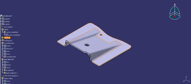
- Obtain Class A Surface and conduct a connection check to see whether the surface has any defects (gaps) between them.
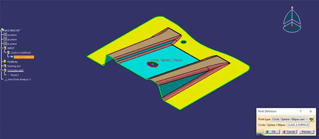
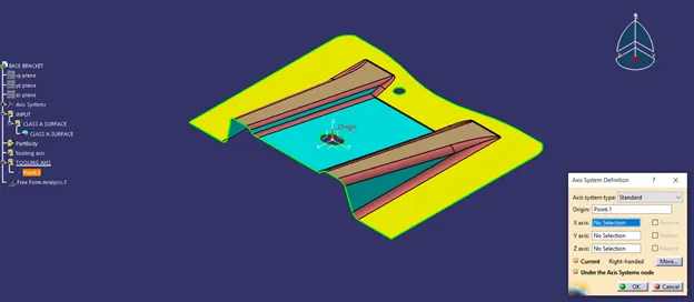
- INSERT AXIS
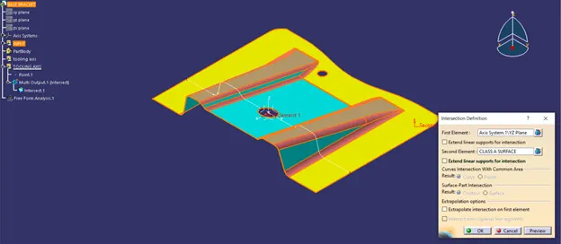
- After creating plane with the help of intersection curve command create an intersection curve on the plane by selecting the required surfaces.
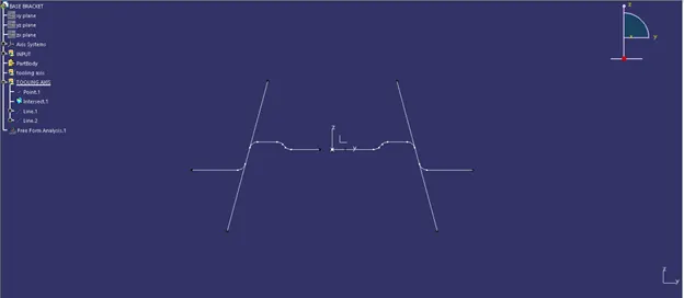
- Next step is to create tooling axis with the help of bisecting lines command.
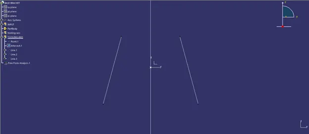
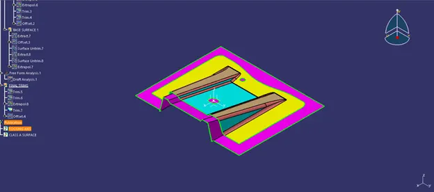
- After creating tooling axis perform feature draft analysis on the class A surface.
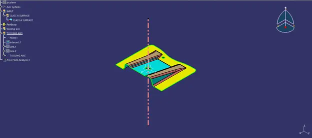
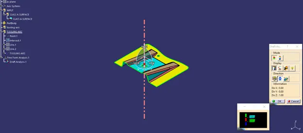
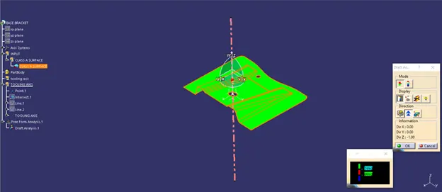
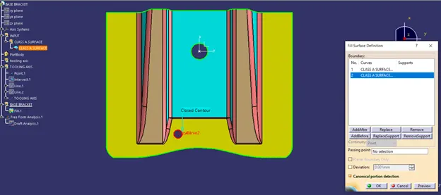
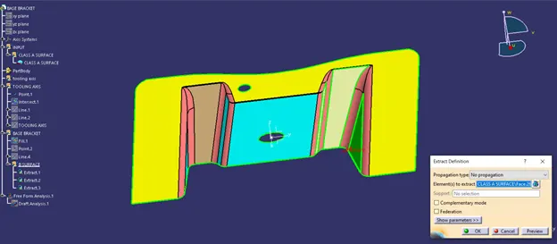
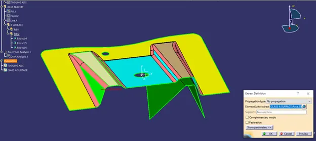
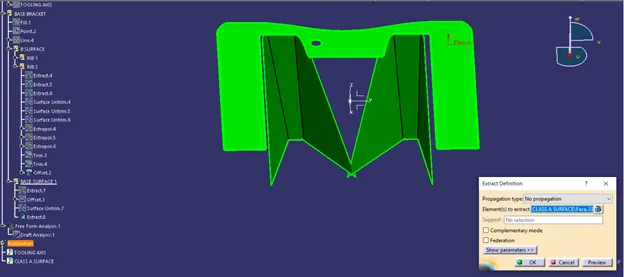
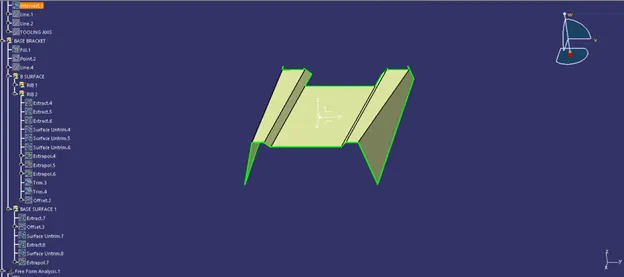
- The next phase is to produce a class B surface, also known as an engineering surface, on which all of the fittings will be manufactured. Class A surfaces are known as aesthetic surfaces since they will not be subjected to operations. To make a class B surface, use the extract command to extract the rib surfaces.
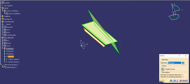
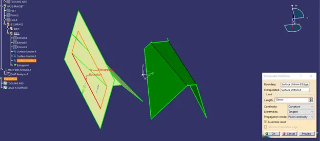
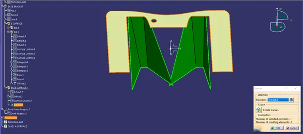
- Untrim those surfaces and extrapolate them by selecting the edge of the surface and by selecting the sheet with point continuity.
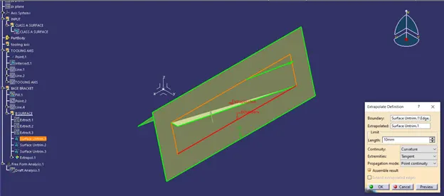
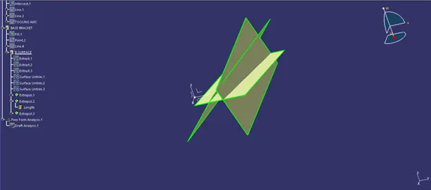
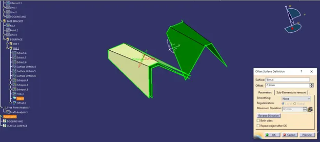
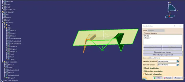
- Trim the excess portion of the sheet and offset them to create class B surface.
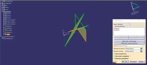
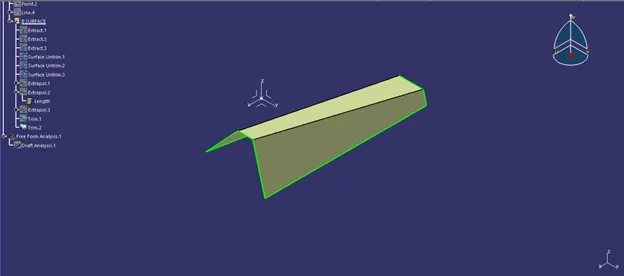
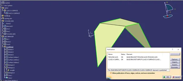
- Repeat for the other.
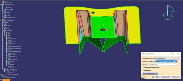
- The base surface of the class A surface of the base bracket must be extracted as well.
- Remove any gaps in the surfaces by untrimming them.
- We may check connectivity with the boundary command to make sure this is the case.
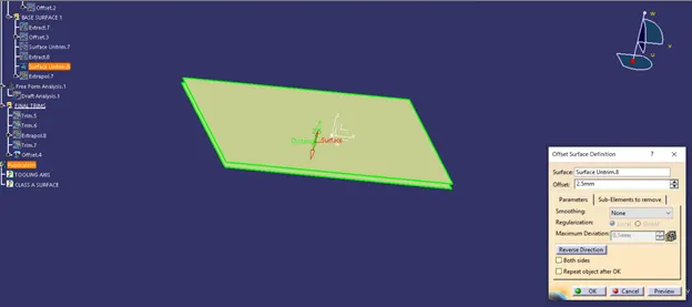
- The next stage is to offset them to form a class B surface, with a 2.5mm offset applied in all situations.
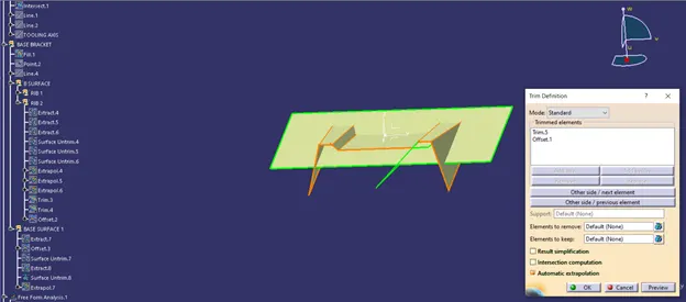
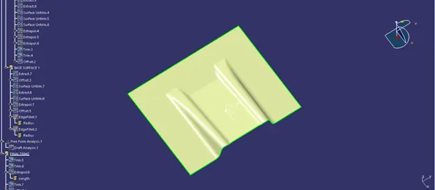
- Extrapolate them and apply the trim command to get the base bracket's exact profile.
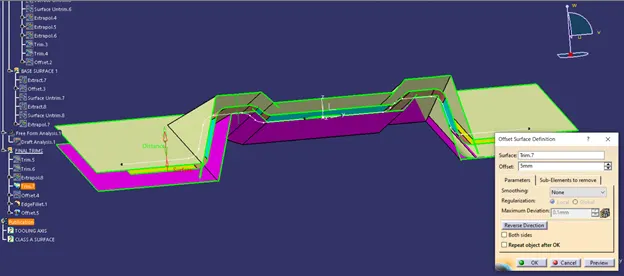
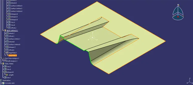
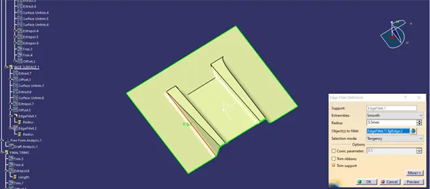
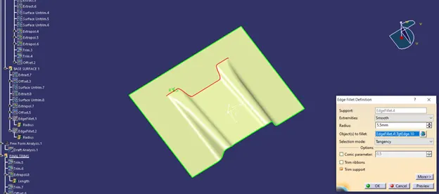
- Use the edge fillet command to apply the needed fillets to the surfaces; in all cases, 3mm fillets were applied.
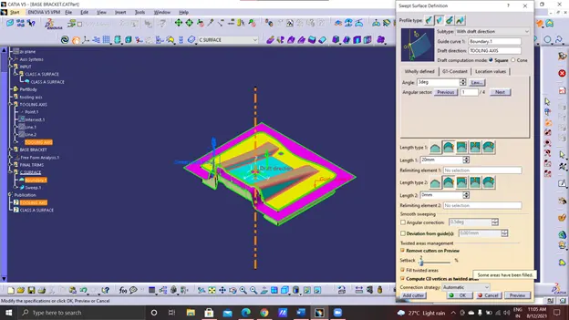
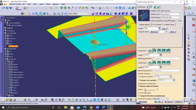
- Using the sweep command, create a class surface by selecting the draught direction and the profile to be swept, which is the profile obtained with the boundary command. Create a class C surface by selecting the profile and selecting the tooling axis direction.
- Boundary command must be used to extract holes given on the class A surfaces. This generates a profile, which must be swept with the sweep command, with the draught direction as the tooling axis.
- Connect surfaces from classes A and C.
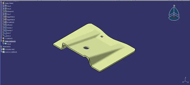
- Using the trim command, choose the join that has been produced and the class B surface to remove the extra piece of the class C and B surfaces.
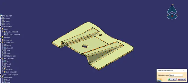
- To convert a surface to a solid, go to the component design module and use the close surfaces command.
- Conduct a draft analysis.
Conclusion:
Class B and C has been created and performed draft analysis for the given class A surface.