Week - 4
Challenge 4
AIM:
- Use stateflow to implement the control logic of a washing machine by specifying certain conditions based on the power and water inputs. According to this input machine, it runs and generates output using lamp light.
- Create the stateflow for gear shift, varying the speed as input, and displaying the result as the gear number.
Objectives:
1.Using Stateflow, comprehend and implement the logic control of a State Machine.
- The system is engaged if a power supply is present.
- If a water supply is not available, halt the procedure and indicate with an LED.
- The soaking duration should be 200 seconds, followed by a washing time of 100 seconds.
- After that, the rinse cycle lasts 20 seconds and the drying cycle lasts 50 seconds.
- After all of the operations have been completed, turn on the completed LED.
Washing machine
Washing machines are generally of 2 categories as follows
- Semi-Automatic Washing Machines -
The semi-automatic is required for your assistance in completing the task, and you will have to manually pour the water and set the timer.
- Fully - Automatic Washing Machine -
Fully automatic washing machines are more convenient and have a wider range of functions. You get fully automatic washing operations that do not require any manual intervention. They are rather budget-friendly, and you will not have to pay a large sum of money to get them. The Fully Automatic washing machine is further subdivided into two sections.
3.Front Load Washing Machine -
You use the front doors to load the drum, and the drum washes, rinses, and spins the laundry. Here you can observe the different operating concept, as the garments tumble from one way to the other as the drum moves. The majority of front-loading washing machines use an agitator washing type to rinse and wash the garments.
4.Top Load Washing Machine -
In this machine, you load the washing machine from the top, and the drum does not move from one direction to the other, but the machine's base rotates and thoroughly moves the garments. To fully wash the garments, the machine's base rotates clockwise and anti-clockwise.
The four processes are:
SOAKING:
It is used to clean garments by dipping them in detergent water. In this function, the customer must choose a soak from a panel. Soak - This feature is accessible with the wash timer; in 42 minutes of washing, 27 minutes are spent soaking, and the remaining 15 minutes are spent washing the garments.
WASHING:
A huge plastic agitator (green) spins around during the wash cycle, propelling your garments through the water. When the wash cycle is complete, the pump empties the water from the outer drum.
RINSING:
The unclean, soapy water is emptied, and your garments are "rewashed" in clean water. Spin: After thoroughly draining the water, your clothing is spun at high speeds to eliminate extra water using centrifugal force.
DRYER:
They function by forcing warm dry air through your wet laundry to extract moisture, then cooling the now-humid air in a heat exchanger to condense the moisture, which is collected in a tank or sent down the drain. The (now dry) air is reheated, and the cycle begins again.
Blocks Used:
Constant: - The constant block generates a signal with a constant value that might be real or complex. This block is used to provide a constant signal input. The block produces scalar, vector, or matrix output depending on the model.

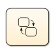
Flowchart: - Implement logic control of the washing machine.
Lamps: - Glows according to the allotted signal.

Display: - It displays the outcome of the input data used to perform the simulation.
CONTROL LOGIC OF WASHING MACHINE AND EXPLANATION:
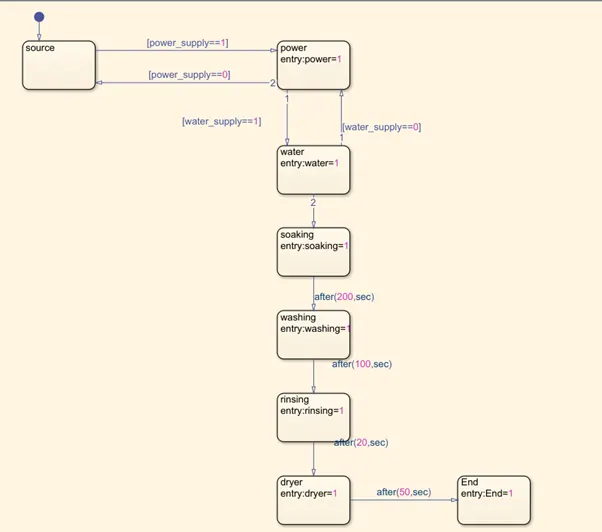
Insert the chart and use stateflow to develop the logic system in Simulink to create this control system. If the condition is acceptable, the stateflow will execute the flow of inputs. The input power is applied to turn on the washing machine in this control logic, and the power supply is flowed in another system. The conditions are used to move other operations in the stateflow sequence. Water supply is activated when the electricity is turned on, therefore entrance and exit are assigned values ranging from 0 to 1. When the situation is not good, the water supply is cut off, and it returns to its normal state. This process is used for each flow, and the time spent working in each operation is initiated by the seconds specified in the inquiry. The stateflow of a washing machine has been constructed and is displayed below.
Now that the input values of steady flow have been supplied, the sequence of operation is being initiated to identify the working division. A constant block is established to provide the system's input power value. Another constant block is built for water supply input and value as 1 to turn on water and conduct the washing procedure. Each sequence includes a display block that displays the results of operations. A lamp block is used to show whether the operations are 'ON' or 'OFF' in various situations.
RESULT:
Simulink models are developed, and inputs to the electricity and water supplies are generated. When the electricity and water supplies are assigned the 0 value, the output value of all activities becomes zero because no inputs are generated and no conditions are applied. Because the operation system is set to 'OFF,' the lamp is red. These are shown below,
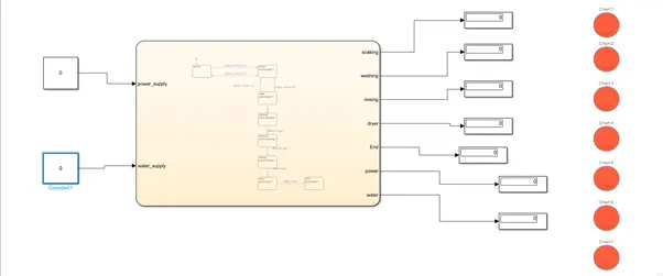
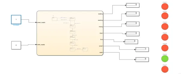
In this stage, power supply is assigned the value 1 and water supply is assigned the value 0. The power is generated, and the lamp with display value 1 is lit up in green. However, because the water supply is 0, other processes are halted, and the lights is illuminated in red.
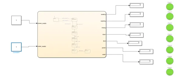
Now the power supply and water supply value are assigned as 1. Power is generated from input and the operation starts; water supply also done by initiate the value of 1. Sequence of operation in stateflow starts when the condition is getting satisfied. Water supply is generated and other operations are followed by duration of time that we give in stateflow. Each operation are runner and results are obtained by display block. Lamp is turned "ON" and it indicates green color as result.
Conclusion:
We successfully created a Simulink model to design control logic for a Washing Machine using Stateflow, as well as simulate a normal washing machine cycle.
GEAR SHIFT:
A manual transmission, often known as a manual gearbox, a standard transmission, or colloquially as a stick shift in some countries (e.g., the United States), is a type of transmission used in motor vehicles. It employs a driver-operated clutch, which is typically engaged and disengaged by a foot pedal or hand lever, to regulate torque transfer from the engine to the transmission, as well as a hand-operated gear selector. A standard 4- or 5-speed manual transmission is generally standard equipment in a modern base model car, with 4-speed transmissions being more popular in non-passenger vehicles such as pickup trucks and light commercial vehicles. Higher-end automobiles, such as sports cars and luxury vehicles, are frequently fitted with a 6-speed transmission as the standard model.
SIMULINK MODEL:
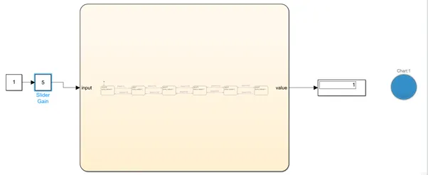
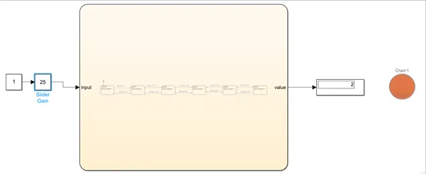
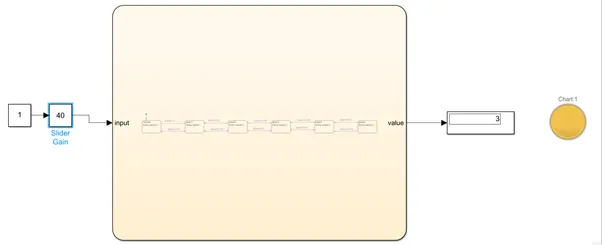
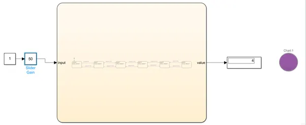
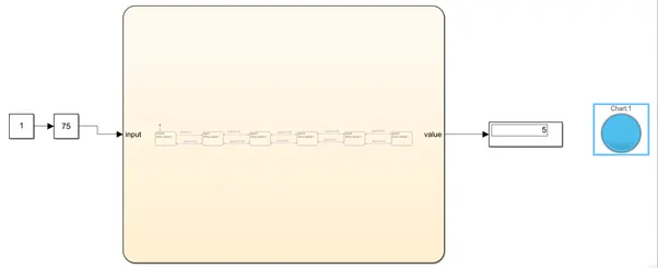
In this model, inputs are created to a slider gain that is coupled to a constant block with the value 1. Conditions in stateflow control the gear shift. The chart is constructed, and the same conditions as in the washing machine stateflow are applied. Variations in speed move the gear. As various gear systems and conditions are applied, a speed range is formed in the chart. To retrieve the result, the display block is used. This shows which gear is active in a certain speed range. A lamp is linked to show the five various colours associated to each gear. The model is shown below,
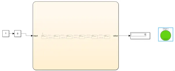
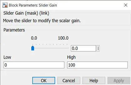
The speed variation is determined by the value entered in the slider gain parameters. When the speed range changes, the output values of the gear are likewise affected by the stateflow conditions.
Results
Neutral
When the speed range is zero, the gear is neutral, and the output value of the display is zero, indicating green light in the lamp block.
Gear - 1
When speed range is 1 to 15 the gear 1 is proceed and output value of display gives 1 thus it indicates blue light which are assigned in lamp block.
Gear - 2
When speed range is 16 to 25 the gear 2 is proceed and output value of display gives 2 thus it indicates orange light which are assigned in lamp block.
Gear - 3
When speed range is 26 to 40 the gear 2 is proceed and output value of display gives 3 thus it indicates yellow light which are assigned in lamp block.
Gear - 4
When speed range is 41 to 60 the gear 4 is proceed and output value of display gives 4 thus it indicates purple light which are assigned in lamp block.
Gear - 5
When speed range is 61 to 80 the gear 5 is proceed and output value of display gives 5 thus it indicates blue light which are assigned in lamp block.
Conclusion:
We successfully created a Simulink model to implement "Gear Shift" logic with stateflow by changing the speed input while the simulation was running and displaying the gear number.