Week 9 - Project - Master Section Development
Week 9 - Project - Master Section Development
Objective:
To create a Closed Body from the given Class A surface of a B-pillar of a car and to model B side features and attachments based on the Master Section input.
Role of a Master Section:
Master sections are the guides for design requirements which decide the component packaging after technical (Styling, Concept or Class-A) surfaces.
Process:
Creating a Closed Body
The given Class A surface was observed at first for any gaps or imperfections. These imperfections were corrected and a proper Class A surface was obtained.
The Class A surface was then compared with the provided Master Section Input.
Flanges observed on the master section had to be created first, to modify the Class A surface of the B-Pillar. Reference geometries were created first and they were checked against the master section. The flanges were then created using the Sweep function.
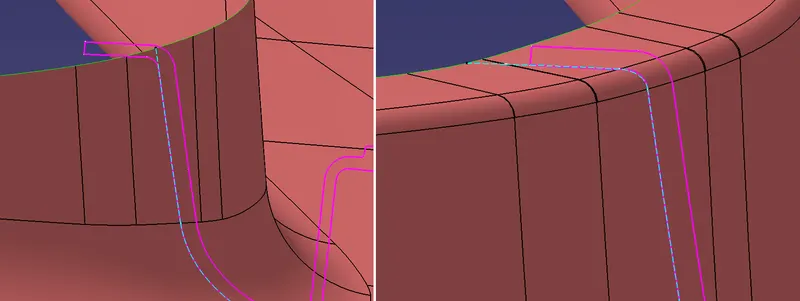
Before and after Flange creation (Blue dotted line represents the surface)
Any surface gaps were repaired using the Multi-sections Surface tool and creating splines with the correct constraints to act as guide curves.

The New Class A surface was offset to 2mm to obtain the Class B surface.
The formation of the Class C surface was not straight-forward since the model contains several curved edges. Therefore several sweep surfaces, Multi-section surfaces and extrapolations were made before they were all trimmed together to form one continous C surface.
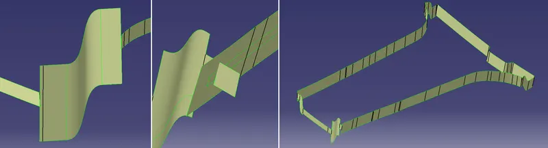
The Class A was then trimmed with the the B and C surfaces to create one closed body made of surfaces.
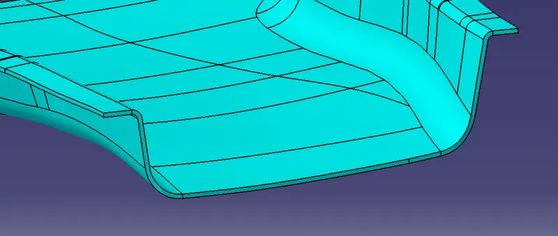
The Close Surface tool in Part workbench was then used to create a Closed Body of the B-pillar.
Creating engineering features and attachments
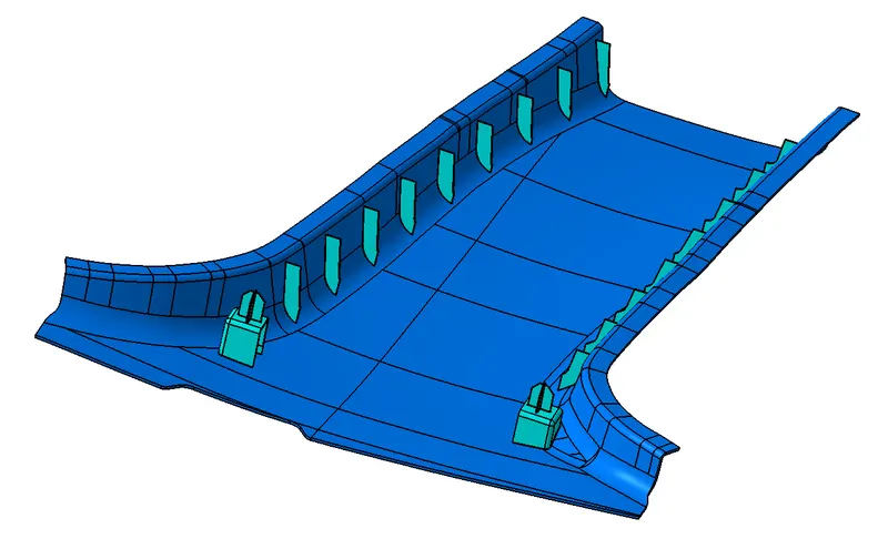
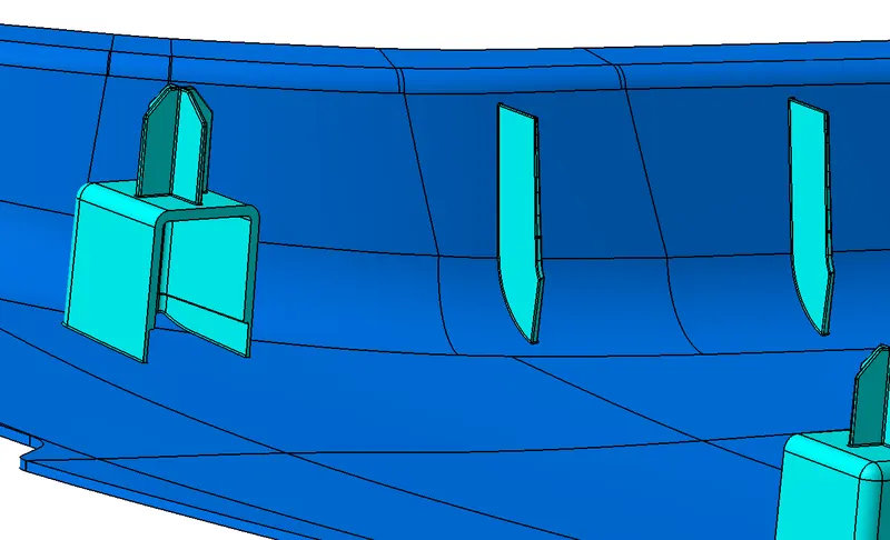
- The engineering features required by the given master section were two Locators mounted on doghouses.
- The Master Section curves were extracted to create accurate surfaces for development.
- Doghouses were designed using extruded, extrapolated and trimmed surfaces.
- The Final Body was achieved using the Close Surface tool.
- Material is removed in the bottom of the doghouse. This is done to avoid sink marks in the component while manufacturing. This process of called "coring" a doghouse was done using the split command to split the solid body.
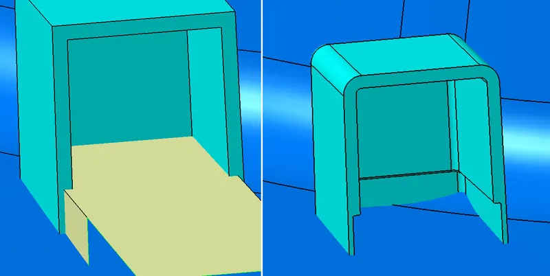
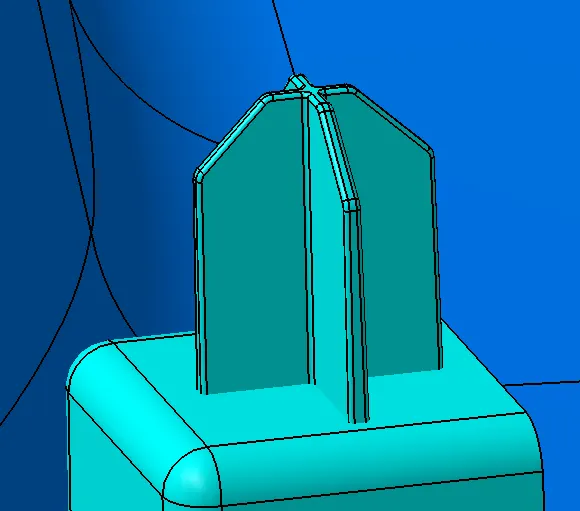
- 4-way Locators were then created and mounted onto the top surface of the doghouse structure.
- Ribs are commonly used to provide additional support and strength to a part.
- Several Ribs were created along the walls of the B-Pillar to provide additional support.
- A parallel curve was created from the boundary edge and new points were added on it. A single Rib was modelled and translated "point-point". To follow the maximum allowed height requirement, the B surface was extracted and offset to trim the rib structure.

Draft Analysis
- The material mode was first selected in the view customization parameters. This setting is required for the Draft Analysis tool.
- The compass was used to create the draft direction for the component.
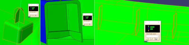
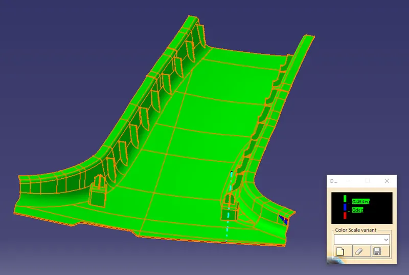
- The elements to be analysed were chosen and the Colour Scale displays the range of draft angles within the component. The standard maximum allowed draft angle of 3 degrees for plastic components was entered in. However, since Ribs, locators, etc., are required to have a minimum draft angle of 0.5mm due to their overall thickness being lesser, the allowed value is changed to 0.48mm.
- The given model passed for draft analysis.The running point option was used to check specific surfaces within the component which may seem parallel or almost parallel to the tooling axis or pulling line.