Week 8 Multi cell Battery Pack
Week 8 - Multicell Battery Pack
Objective
To explain how the weakest cell limits the usable capacity of the battery pack and to propose its solution
Question
How weakest cell limits the usable capacity of the battery pack? What is the solution?
Explanation
The weakest cell limits the usable capacity of the battery pack:
No two cells are identical. There are always slight differences in the state of charge, self-discharge rate, capacity, impedance, and temperature characteristics. This is true even if the cells are the same model, same manufacturer, and the same production lot. Manufacturers will sort cells by a similar voltage to match as close as possible, but there are still slight variations in the individual cell's impedance, capacity, and self-discharge rate that can eventually lead to a divergence in voltage over time.
Cell balancing is the process of equalizing the voltages and state of charge among the cells when they are at a full charge.
Types of cell balancing:
- There are two popular ways of balancing, namely passive balancing and active balancing.
- The conventional passive balancing method prevents the bleeding of excess energy from cells into heat, while in active balancing there is a transfer of the excess energy into energy-depleted cells.
- Both typologies have their respective pros and cons.
Passive cell balancing:
Passive balancing allows the stack to look like every cell has the same capacity as the weakest cell. Using a relatively low current, it drains a small amount of energy from high SoC cells during the charging cycle so that all cells charge to their maximum SoC. This is accomplished by using a switch and bleed resistor in parallel with each battery cell.
- The high SoC cell is bled off (power is dissipated in the resistor) so that charging can continue until all cells are fully charged.
- Passive balancing allows all batteries to have the same SoC, but it does not improve the run-time of a battery-powered system. It provides a fairly low-cost method for balancing the cells, but it wastes energy in the process due to the discharge resistor. Passive balancing can also correct for long-term mismatch in self-discharge current from cell to cell.
The above figure shows the basic diagram of a typical shunting resistor passive cell balancing. This topology supports the simultaneous balancing of multiple cells and achieves the balancing by dissipating energy from energy-filled cells in the respective resistors.
The important factors for consideration of this architecture are, the Resistance sizing with balancing current and balancing time. Also, the thermals for heat dissipation need to evaluate to eliminate the degrading of the system. In general, the onboard passive balancing current ranges from a few hundreds of milliamperes to around 1 Ampere, and hence the effective balancing time calculations heavily depends on balancing current. Also, the balancing current is directly proportional to cell voltage, and hence it is not constant throughout the charge cycle.
There are possible tweaks in the basic architecture to enable it for a larger balancing current but eventually, it's a trade-off for balancing current and required balancing time with the cost. The overall architecture and implementation of passive balancing is very economical with reduced complexity.
Active cell balancing:
In this example, full capacity is shown as 90% of charge because keeping a battery at or near its 100% capacity point for long periods of time degrades lifetime faster. 30% represents fully discharged to prevent deep discharge of the cells. Over time, some cells will become weaker than others
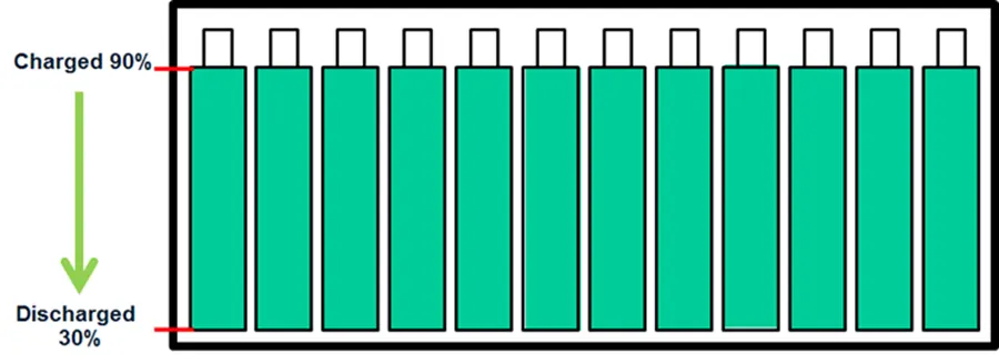
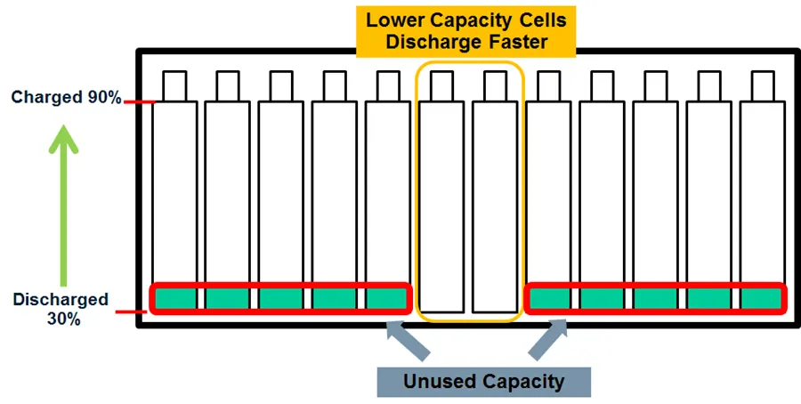
Active cell balancing is a more complex balancing technique that redistributes charge between battery cells during the charge and discharge cycles, thereby increasing system run time by increasing the total useable charge in the battery stack, decreasing charge time compared with passive balancing, and decreasing heat generated while balancing.
- Active cell balancing topology manages to transfer the charge from energy exceeded cell to energy-depleted cell via bi-directional DC-DC power converter circuits. There are several types of active balancing methods based on the type of energy transfer.
- The energy transfer can be from one cell to the whole battery, from the whole battery to one cell, or from cell to cell. The following figure is typical circuitry for the cell to pack the energy transfer section.
The balancing current and balancing time is completely dependent on the control logic and efficiency of DC-DC converters. In general, there is no theoretical limit for balancing current but the balancing current per cell should be below the typical discharge current given in the datasheet (most of the Li-Ion cells recommend 1C as ideal discharge current). The overall active balancing is relatively more expensive than passive and needs a lot more complex hardware and firmware.
With active balancing, the charge is redistributed from the stronger cells to the weaker cells, resulting in a fully depleted battery stack profile.
Widely adopted solution:
Active cell balancing is an amazing way to handle the cell balancing problem, but, in terms of system integration and optimization, this approach takes a hit on many fronts like cost and complexity. With improved battery cells and new cell chemistry, the battery variation is stabilizing. Hence, passive balancing is a widely accepted approach for most of the applications, while having some exceptions.
References:
https://www.ionenergy.co/resources/blogs/cell-balancing-better-performance/
https://www.batterypoweronline.com/blogs/why-proper-cell-balancing-is-necessary-in-battery-packs/