Project - Master Section Development
AIM:- Design for B Pillar master section development
INTRODUCTION:- Pillars are those vertical component of car which provide structural support roof-top and is designed for latching the front door and mounting the hinges of rear door. Pillar are divided into 3 type A,B,C in sedans but can go to D for SUV.
In this project we are designing B pillar which is between front door and rear door. Desiging of B pillar can be further divided into two major part, one is trim which we are going to design with engineering feature and other is BIW on which trim is going to get attached. B pillar trim will come inside the car and is made of plastics and B pillar BIW will go on the body of car which is made of alloy steel.
INPUTS:- To develop the B pillar we got following as input
- MASTERSECTIONS
- CLASS A SURFACE
EXPLAINATION:-
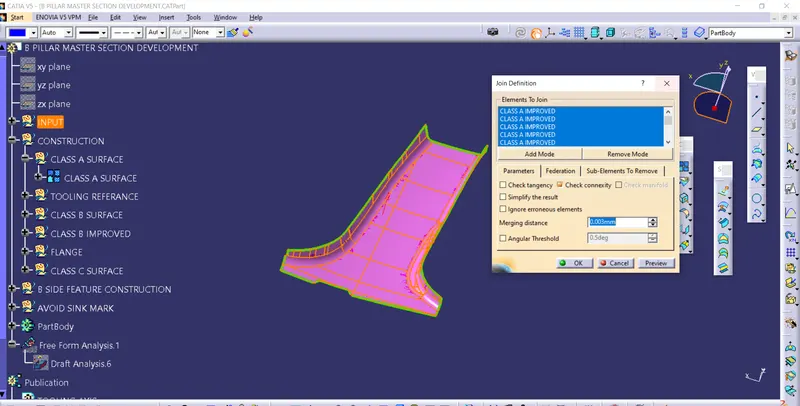
- As we all know that the very first step of designing any component is to check whether the given class A surface bear any type of gap or not. For that we perform boundary,if we find any small gap between the surfaces then we perform join and if we find big gap which cannot be resolved by join then we improve that surface by troubleshooting. Or we can perform join directly to fill the smaller gap of within the range of 0.001mm to 0.003mm.
- Class A surface we got as a input was perfectly fine. We can proceed further by simply joining the surface using join ensuring that thier is no any smaller gaps in between the patches of Class A surface we got.
TOOLING REFERANCE:-
- Under this geometrical set, we have two axis one is tooling axis and another is lifter axis.
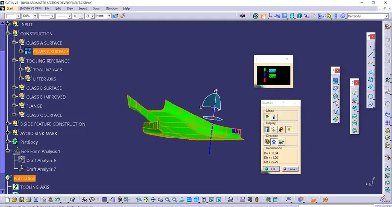
- TOOLING AXIS is being created for the main body, outer face of dog house and locator to give draft for the clearence from core and cavity as the whole component is to be cleared in one direction only and to do draft analysis of the pillar.
- So by using bisecting method, we will be creating tooling axis.
- As per mastersection we have 4 way locator, Extract this edges of locator and create a point in between. Now create a bisecting line in between using point we created. Now we create another bisecting line using the edges of another locator.
- Now bisect the two bisecting line we line this we get our tooling axis.
- Now we change graphics property of the tooling axis to identification from the other line and publication of tooling axis is done for easy use in future.
DRAFT ANALYSIS OF CLASS A SURFACE USING TOOLING AXIS:-
LIFTER AXIS:-
- This axis is created to clear the inner face of dog house.
- As this is same as side core axis but it is not at the edge it is at some distance so it is called lifter and axis used is called lifter axis.
CREATION OF FLANGE:-
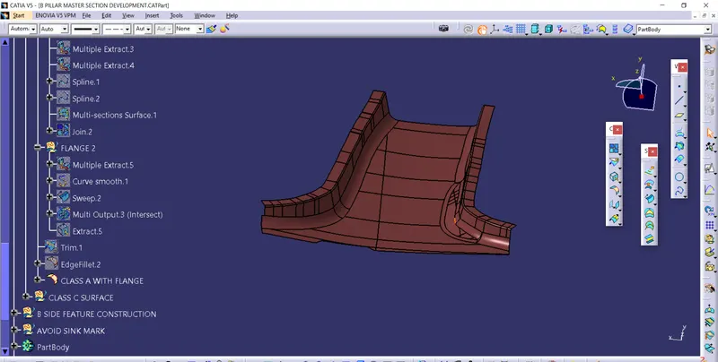
FLANGE FOR CLASS A SURFACE
- FLANGE 1
- Create a palne on mastersection.
- Extract the edge of class A surface and side face of class A surface.
- Create the sweep using with referance surface and using extract 1 and extract 2.
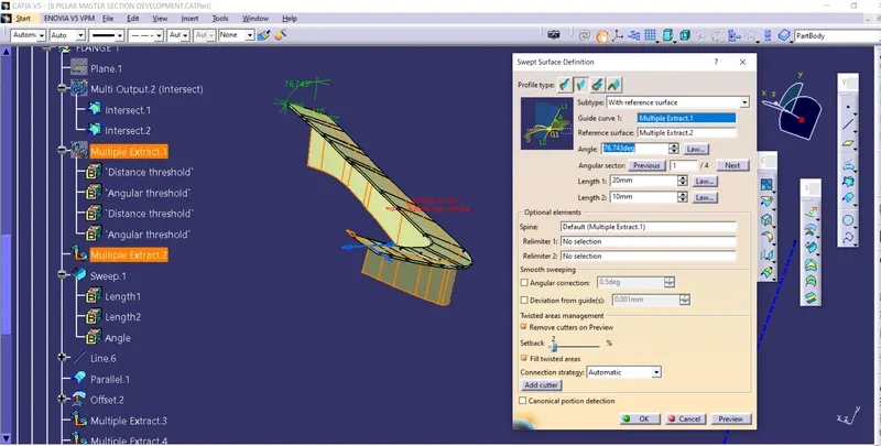
- Now take intersection of the sweep and plane we created to match with the matersection.
- We found that our sweep is not matching the master section so we will improve that by offseting.
- Create a line from the curve of sweep and a parllel line with the mastresection. Now measrue the distance between them and offect the sweep to that distance.
- As our surface is not that continous so will get an error while offset by continouing we will get some edge.
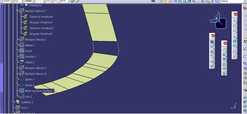
- For troubleshooting this we create a multi-section using spline and extract of surface edges around that gap.
- Now join the multi-section and offset surface.
- Similary process is followed for FLANGE 2.
- Now trim them with class A surface and add edge fillet to them.
- We get CLASS A SURFACE WITH FLANGE.
CREATION OF CLASS B SURFACE WITH FLANGE:-
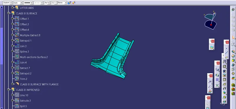
- According to mastersection we know that thickness of component is 2mm.So directly offset the class A surface to 2mm.
- Also offset the two flanges we made for class A surface to 2mm.
- Extrapolate the side wall of class B surface to get trimmed with flanges. When we extrapolate the one side of edge it get extrapolated easily.
- But when we extrapolated other side wall of class B we get error. we trobuleshooted them for correction.
- We delete that portion which is creating error and try to recreate that.
- Using spline and multi-section we fill that deleted portion and join them. Now we extrapolate the edge and we get it easily.
- Now trim the two flanges with class B surface to get the final result.
- We get class B surface with flange as final result after adding edge fillets to trim faces.
CREATION OF CLASS C SURFACE:-
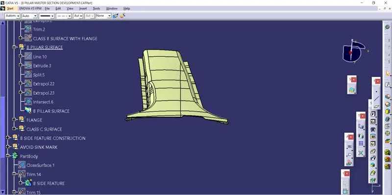
- For creating class C surface we will we divide component into 4 portion and work on them.
- Extract the edge of flange and back portion and create sweep of draft angle of 3deg face outside.
- Trim them with extrapolated class B. Similar operation is performed for other face.
- After getting we join class A surface with trim.
- After making some changes to with class B surface we trim with join to get B pillar surface.
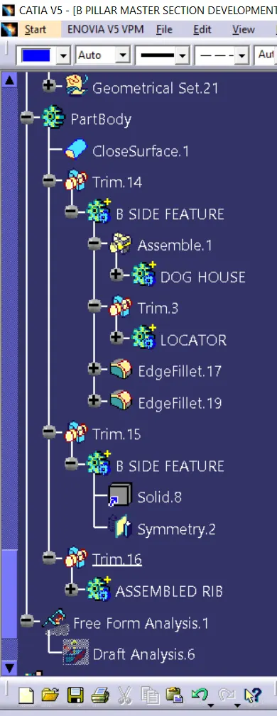
- Now we open part body to create close body.
CREATION OF B SIDE FEATURE:-
DOG HOUSE AND LOCATOR
- Create a sketch for dog house.
- Project the mastersection for creating the sketch of dog house.
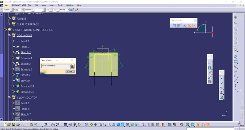
- Now create another sketch and extrude one the line to get surface and offset it to close one side of dog house with some extrapolated length.
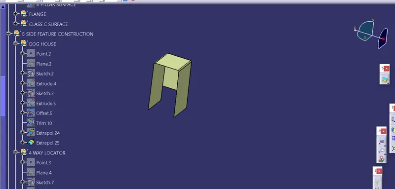
- Now we can insert a body and thicken them.
- Similary, using mastersection will create sketch and extract.
- Pad them using neutral fibre to thickness of 1 mm.
- Add edge fillet to dog house and locator.
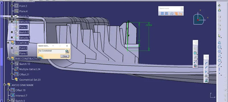
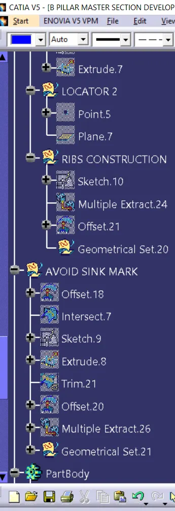
- To avoid sink mark in dog house we have also performed operation.
- Take surface extract and offset it to 0.8mm.
- Now offset class B surface to 4mm and trim them.
- Use this trim to split the dog house to set the design rule.
- Give draft of 0.5deg to inner face with lifter axis.
- For another dog house we simply symmetry them about a plane we create a middle of side edges of dog house given in mastersection.
CREATION OF RIBS:-
- Create a sketch and extrude it.
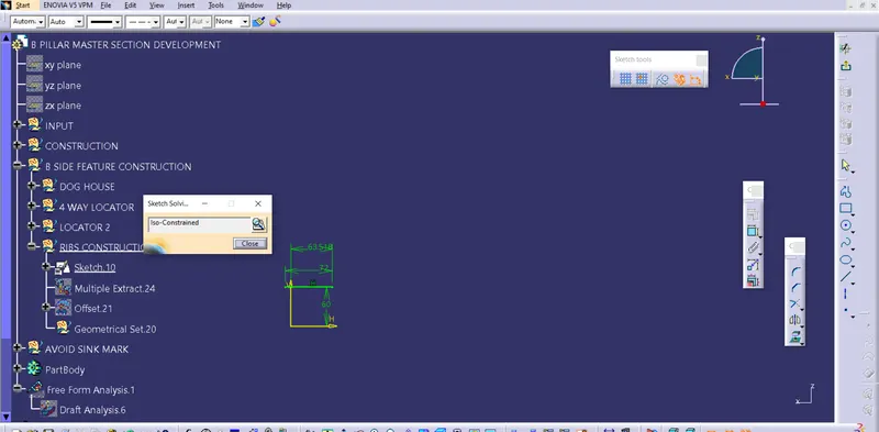
- Now thicken it. And give draft of 0.5deg.
- Now translate it to 50mm apart along the side wall.
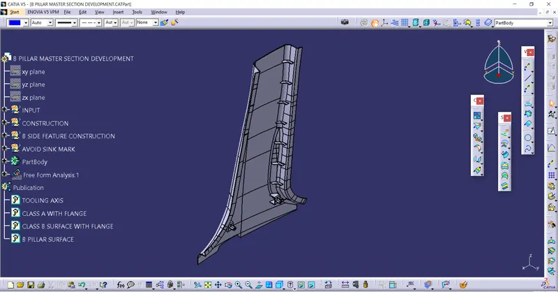
Like this we get our final component with engineering feature which is B pillar.
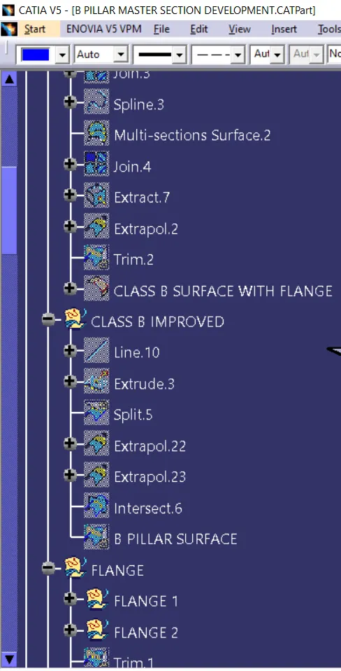
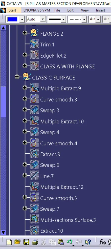
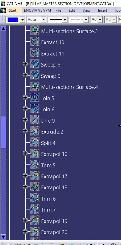
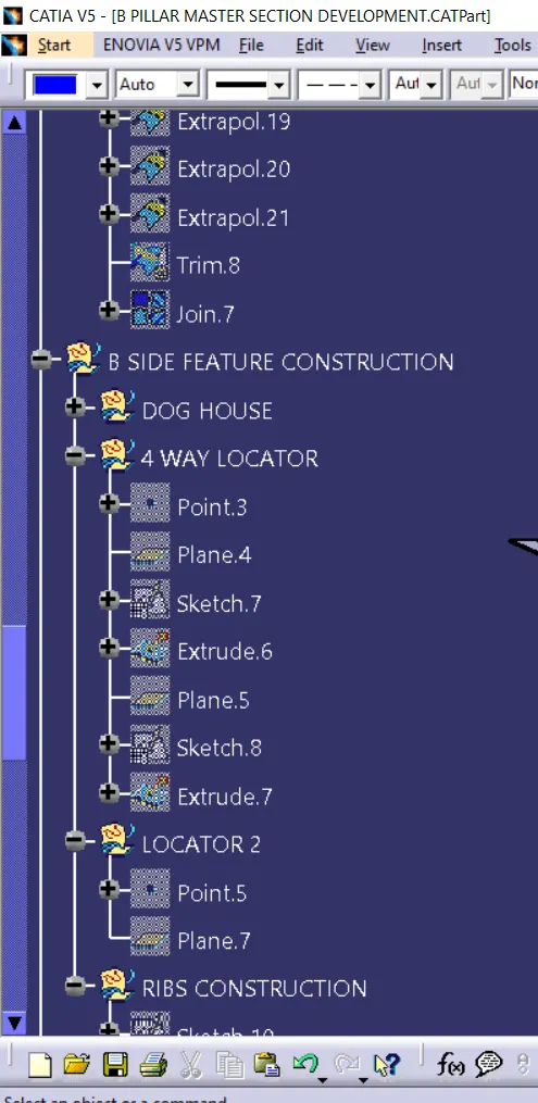
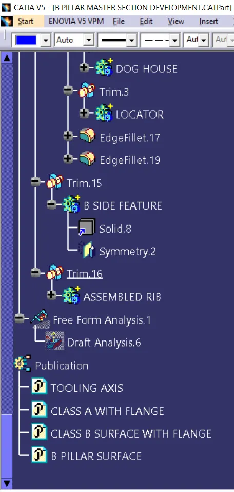
FEATURE TREE:-
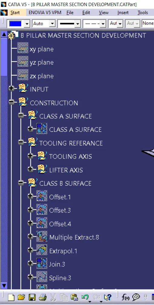
ORIENTATION OF B PILLAR
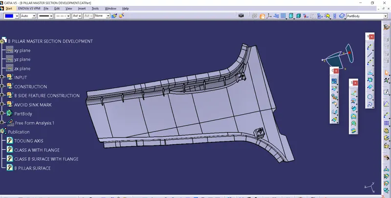
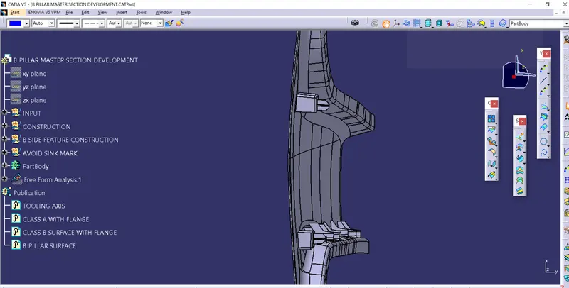
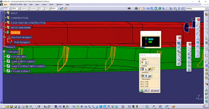
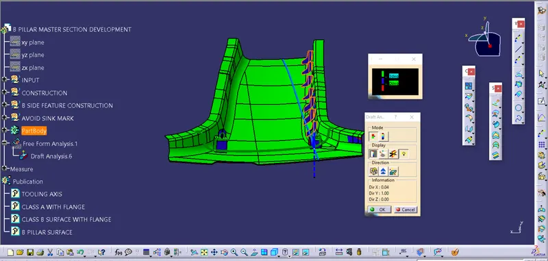
DRAFT ANALYSIS OF B PILLAR
FOR CLASS A AND C SIDE
FOR CLASS B SIDE
THANKYOU