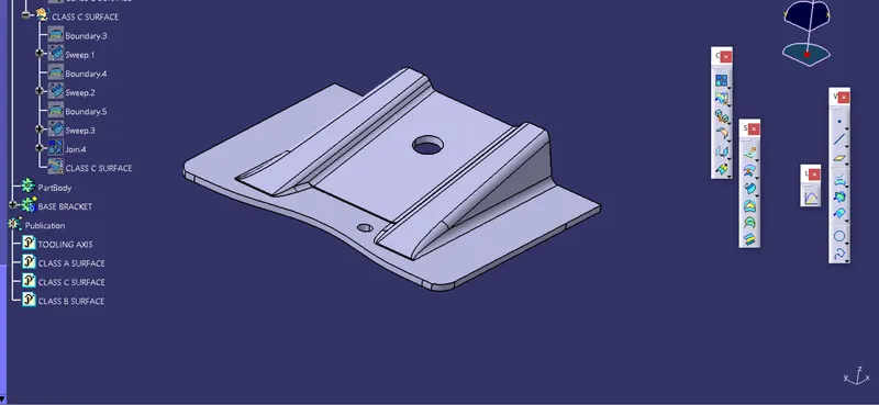
Project - Base Bracket Design
AIM:-TO DESIGN BASE BRACKET USING CLASS A SURFACE AND DOING DRAFT ANALYSIS OF PLASTIC DESIGN
EXPLAINATION:-
- Base bracket class A surface is imported to catia interface.
ERROR
- some gap were found between two surface of class A surface.Then one of the small surface is improved by extracting and joing again by increasing merging distance by 0.003mm.
- Then larger surface boundary is extracted by using multi-extract and surface is filled by surface fill option. Again it is joined by other surface .
TOOLING AXIS:-
- Referance plane is inserted w.r.t YZ plane and point 1 which is created at the centre of big circle.
- plane and class A surface is made to intersect and we get intersection.
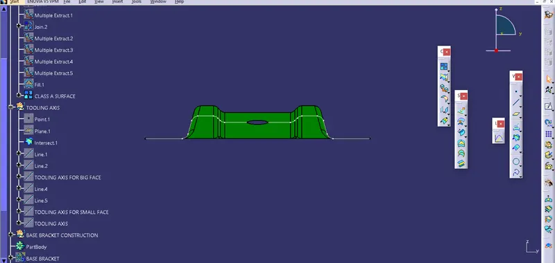
Now here we can observe that thier edges which can cause problem during ejection. So,we will create tooling axis for both using intersection method.
- Two lines are drawn line 1 and line 2 taking points as referance.
- Now one more line is drawn using bisecting option and taking line 1 and line 2 as referance. This tooling axis for this face and similarly one more tooling axis is created for another face.
- Now tooling axis for big face and tooling axis for small face is bisected again and this axis is our main tooling axis.
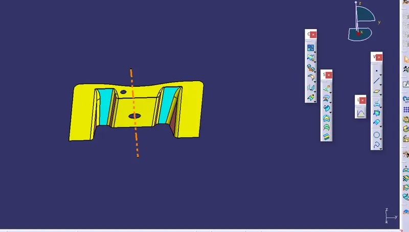
CREATION OF CLASS B SURFACE:-
- Parts are differentiated into some small parts like rib1, rib2, base.
- we will create rib1 and same process is followed for rib2 and base also.
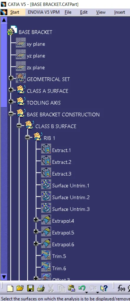
- extract the faces of rib1 using multi-extract.
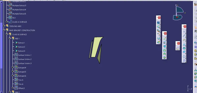
4.Now untrim them.
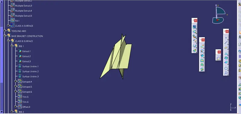
5.Now extrapolate them.
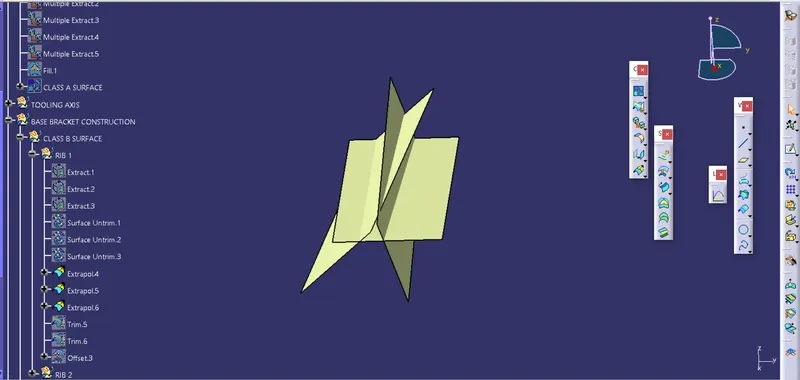
6.Then trim them and then offset them by 2.5 as thickness of component is 2.5mm
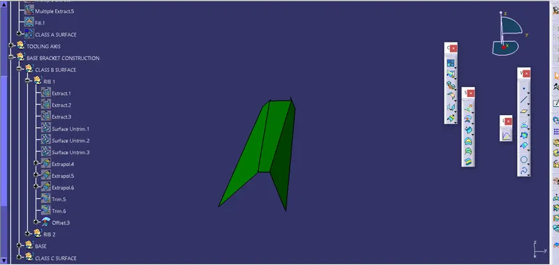
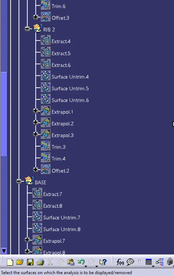
Now we can say that this is CLASS B SURFACE of rib1. similary process is followed for rib2 and base.
7.Finally we trim rib1, rib2 and base to get class B surface.
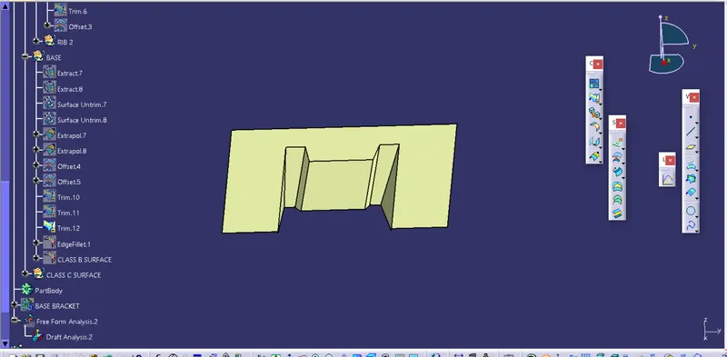
8.Fillets are not easy to make at intial time so we will give edge fillet here and we will get our Final Class B surface.
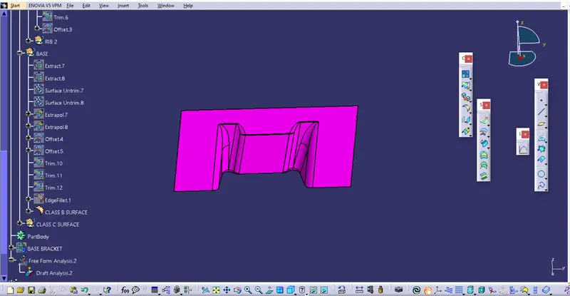
CREATION OF CLASS C SURFACE
- we perform boundry operation with class A surface .
- Now we perform sweep operation with draft direction along tooling axis giving 3degree of draft.
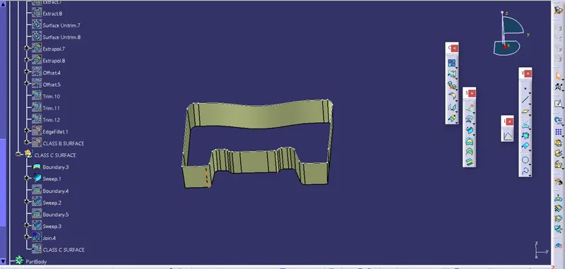
Now we get class C surface and same we do for both holes.
Now class A and class C is joined together and trimed with class B surface.
Finally we get our plastic design.
Now insert new part and use closed body to make plastic design solid.
FEATURE TREE:-
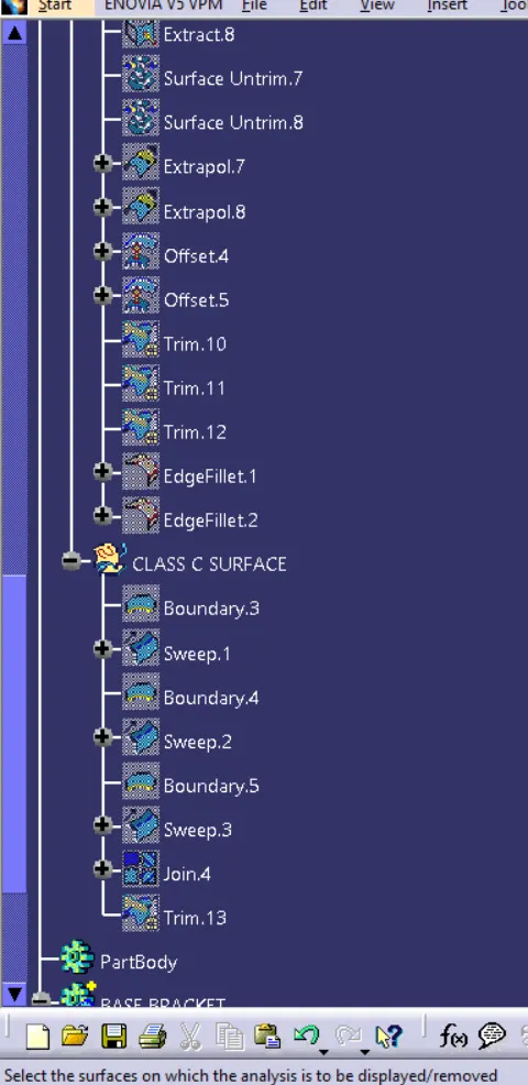
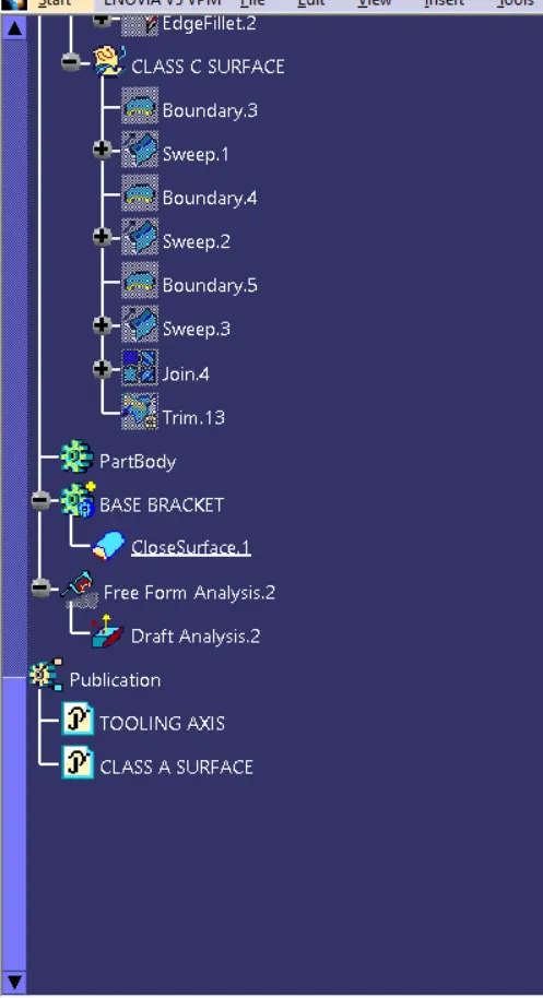
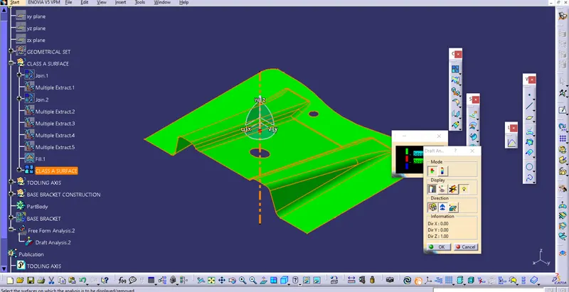
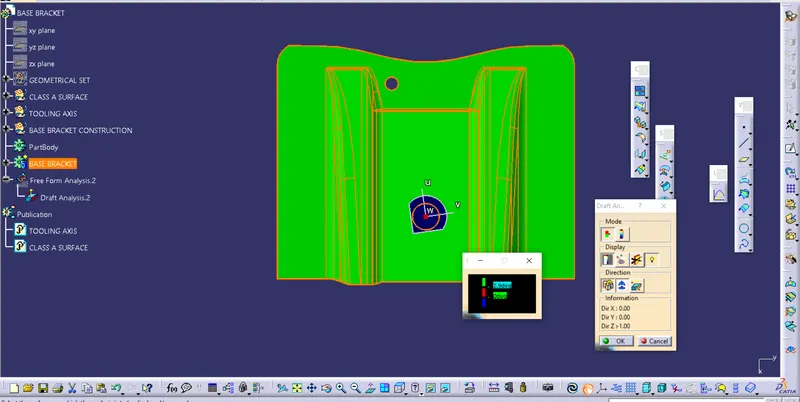
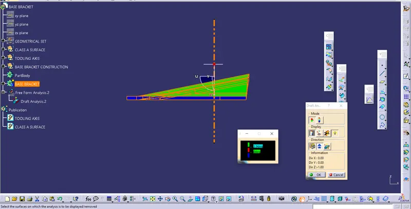
DRAFT ANALYSIS OF CLASS A SURFACE:-
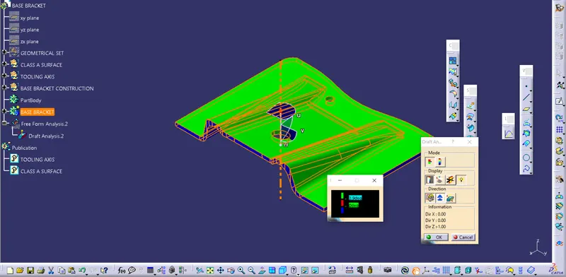
DRAFT ANALYSIS OF PLASTIC DESIGN:-
PUBLICATION:-