SUNSEEKER PREDATOR YACHT
Title of the project:- Surface modelling and assembly of Sunseeker Predator Yacht
Objective:- The main objective of this project is to model a sunseeker predator yacht using mainly surface modelling in solidwork and create photorealistic renders of yatch in solidwork visualize .
Introduction:-In this project, I have modeled the sunseeker predator yacht to understand the 3D modeling of mainly surface modelling and to some extent solid modelling.All the parts of yacth are modeled in solidworks and after assembling all the parts of yacht,it is rendered in solidwork visualize.
Sunseeker Predator Yatch are motor yacht which are 20m-22m long.This yatch is designed to emphasize comfort as well as performance.The parts which it contain and are designed in this project are Hull,Superstructure,Seats,Propeller,Radar,Garage door and Radar Mast.
Design Methodology:-
1.Modelling
2.Assembling
3.Rendering
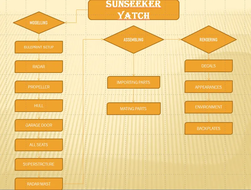
Description of commands:- Majorly,I have used and got to learn, is about surface modelling during the design of this yacth so here we gonna discuss about surface commands.
To create complex surfaces it is very hard to model surfaces in solid modelling.So,basically what we do is first we create surfaces using surface modelling using projected curves,surfaces extrude and varoius tools of surface modelling(which we will discuss further). After creating closed surfaces and in kintting we get option to create solid and like this we convert a suface model into solid model.For this yacth,first we set-up blueprint and then we proceed.
Surface Commands:-
- Extruded surfaces
- Swept surfaces
- Lofted surfaces
- Boundary surfaces
- Filled surfaces
- Offset surfaces
- Ruled surfaces
- Delete faces
- Extend surfaces
- Trim surfaces
- Knit surfaces
- Referance planes
- Projected curve
- Fillets
1.Extruded surfaces:- This command helps us to extrude the selected contour using using various option like blind,up to surface,upto next and etc.It can be extended in both the direction.
2.Swept surfaces:- This command is employed create curved surfaces using profile and path.Thier is option for curvature display of zebra strip,mesh preview and curvature comb.
3.Lofted surfaces:- This command is employed to create surafces between two curves using guided curve which helps us to give a smooth surfaces.
4.Boundary surfaces:- This command lets us to create surfaces just like what lofted surfaces allows but it delivers high quality of result then lofted surfaces.
5.Filled surfaces:- This command helps us to feel the gap wherever needed by selecting the patch boundareis in clockwise or anti-clockwise direction.
6.offset surfaces:- when we want to create a similar surface of selected one but at some distance then we use this command by giving required offset distance.
7.Ruled surfaces:- When we want to create extra surfaces by selecting the edges of the surface using various options present like normal to surface,tangent to surface,tapered to vector etc then this command is used.
8.Delete faces:- When we want to delete any surface then this command is used and the deleted face can be filled also using option like tangent and fill.If we have any solid body and we want it to convert into surface then we delete its one face and solid body is converted into surface as one of its face gets opened.
9.Extend surfaces:- This command is employed to extend any surface by some length by selecting the edge of that surface which is to be extended.
10.Trim surfaces:- Trim surfaces is one the most important command which is used to trim the various surfaces as per requriment.This command has both option either you keep the surface or you cut the selected surface.
11.Knit surfaces:-Thier are many small gaps between two or more surfaces which cannot be seen by naked eyes which will create problems when we will convert surfaces into solids.So,we knit the surfaces by giving proper tolerance.
12.Referance planes:-Extra palnes are inserted to create some geometry by selecting the reference like-edges,vertex where the new plane has be created.
13.Projected curve:-This curve is combination of two different curve in different plane but their both end point coincides.
14.Fillets:- This command is use to round the sharp edges by consuming the material thier.Their are many types of fillets like round fillet,face fillets ,etc.
Description of parts of yacth:-
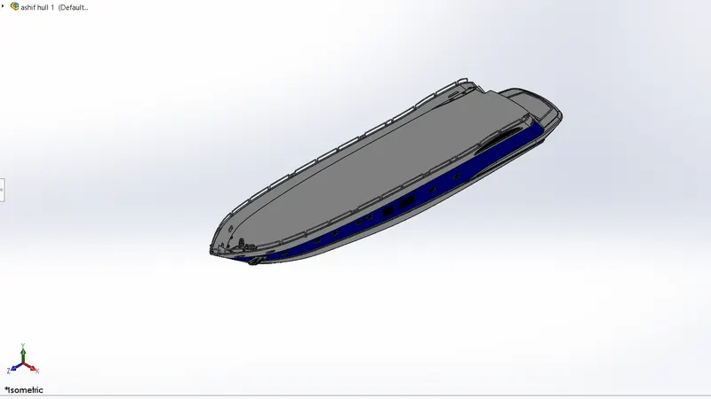
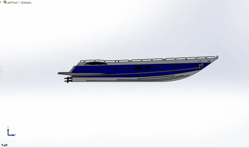
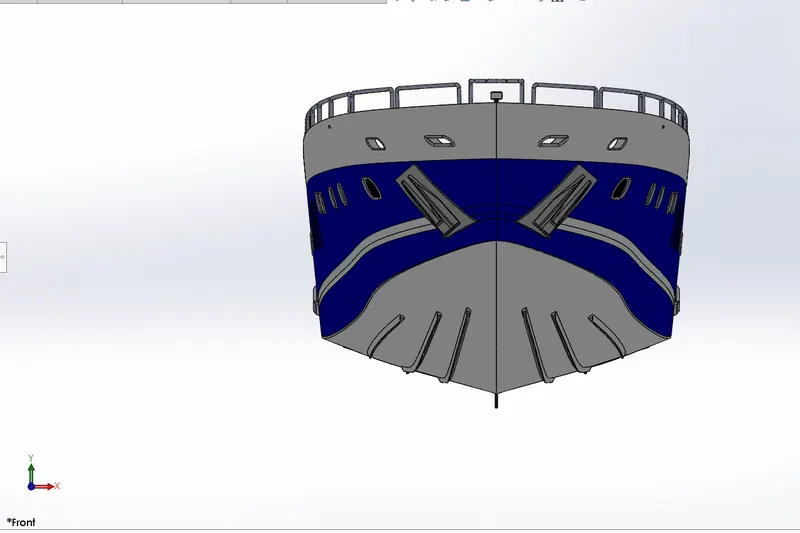
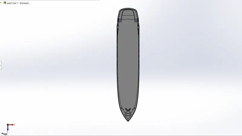
1. HULL:- The hull is the most notable structural entity of the yacth.It is fully or partially covered with a deck surface which is base for the superstructure,seats ,etc.Hull itself contains many parts like basline,bow,port,starboard,stern,etc.First two projected curve are drawn and by using two more sketch these two projected curve is closed and then lofted surface is applied and using this as a base surface more surfaces are created to mid-plane during this trim surfaces and knit surfaces are used and then surfaces are closed by using fill surfaces command and then it is converted into solid body.Shell is performed to convert into shell and give thickness to hull and like this we proceed in the making of hull.
Commands employed:-
- Sketch
- Projected curve
- 3-D sketch
- Slot
- Spline
- Line
- Extruded surfaces
- Lofted surefaces
- Surface fill
- Trim surfaces
- Knit surfaces
- Extrude boss
- Extrude cut
- Sweep
- Pattern
- Revolve boss
- Mirror
- Split
- Helix
- Chamfer
- Dome
Some orientation of hull:-
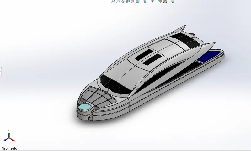
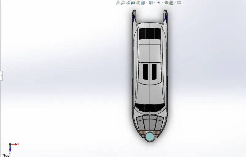
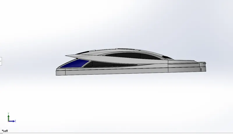
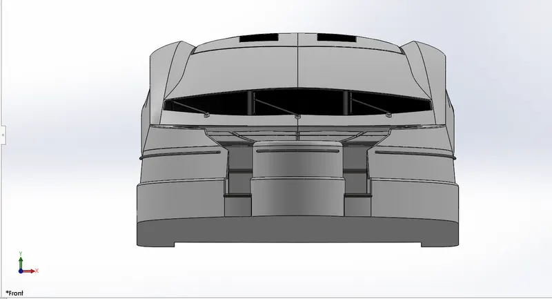
2. SUPERSTRUCRTURE:- Superstructure is an extended construction of the yacth that emerges from the deck.It is base surface for radar mast.It is broader and bigger in size and area.Size of the superstructure has great influence on the mobility and speed.As superstrcuture was complex shape so it was designed by using surfaces commands.Sketches were made using line,splines with the referance of blueprint and then it was surface extruded and sweep was performed to make edge like surface and then ruled surface was performed using inner edge of sweep and then trim was performed to ruled surface and like this we continue in making of superstrcture.
Commands employed:-
- Sketch
- 3-D sketch
- Surface extrude
- Sweep surface
- Lofted surface
- Surface trim
- Kint surface
- Shell
- Fillet
- Chamfer
- Extrude boss
- Extrude cut
- Ruled surface
- Delete face
- Offset surface
- Dome
- Referance plane
Some orientation of superstructure:-
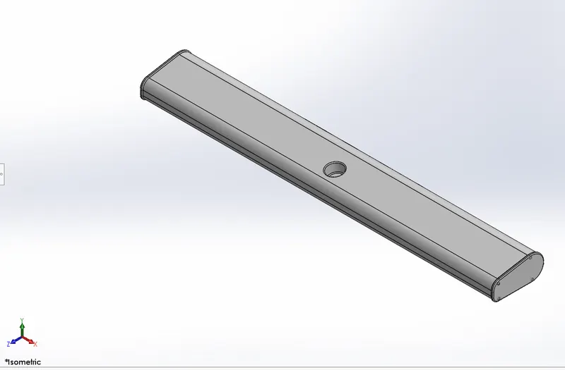
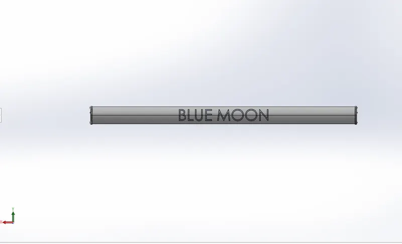
3.RADAR:-Radar are that device which are employed to detect other ships and land obstacles. It provide bearing and distance to avoid collision and navigation at the ocean.For designing of radar we just sketch and for the half of the part and boss extrude it and after adding fillets and performing extrude cut we simply mirror it. Split line command is used to write the name on the face.
Commands employed:-
- Sketch
- Extrude boss
- Cut extrude
- Fillets
- Mirror
- Split line
Some orientation of Radar:-
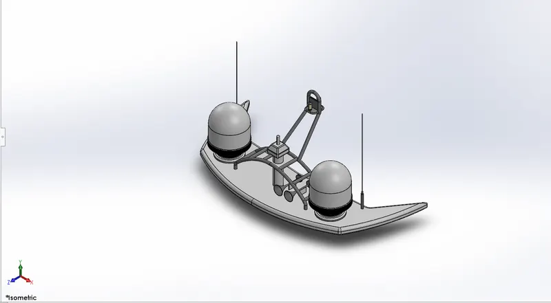
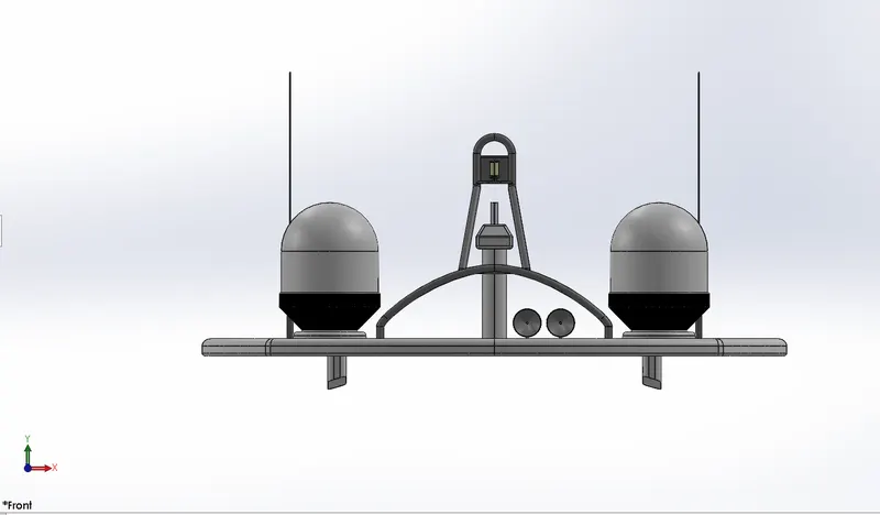
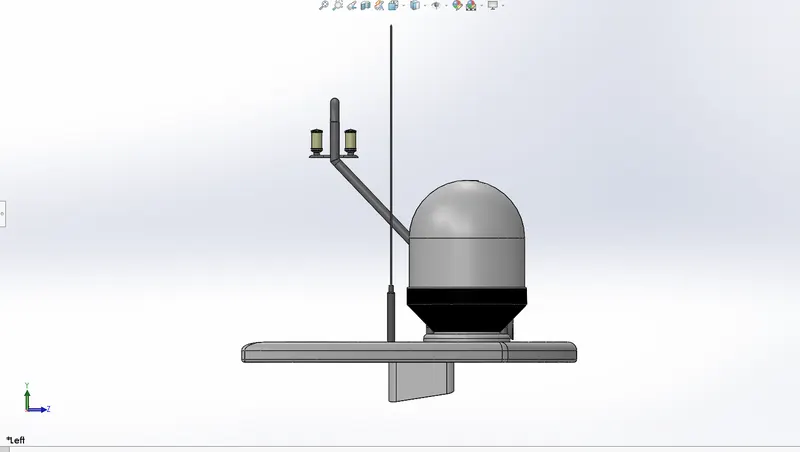
4.RADAR MAST:-Basically ,this is used to hold the radar but it is also responsible for carrying sails,spars and derricks and give necessary height to a navigation light,signal yard and radio aerials, etc.Radar mast was created on surperstructure.with the help of blueprint base is created and on that base sketch is created and revovle is performed for mast and like this we proceed in radar mast.
Commands employed:-
- Sketch
- Boss extrude
- Revolve
- Fillets
- Projected curve
- Sweep
- Chamfer
- Referance plane
- Shell
- Mirror
Some orientation of Radar mast:-
5.GARAGE DOOR:-This is simple a door which has been made by splited material from yacth hull.
Commands employed:-
- Cut extrude
- Shell
- Fillets
- Mirror
Some orientation of garage door:-
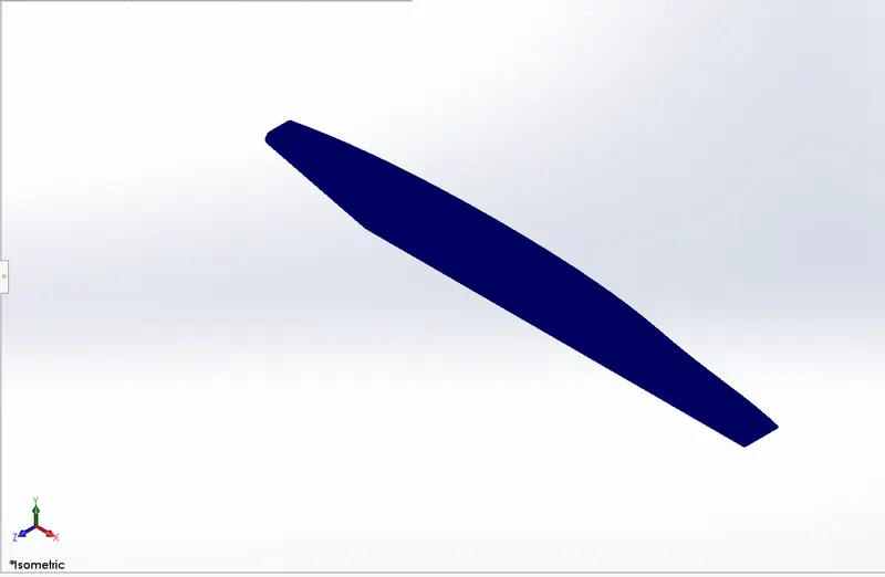
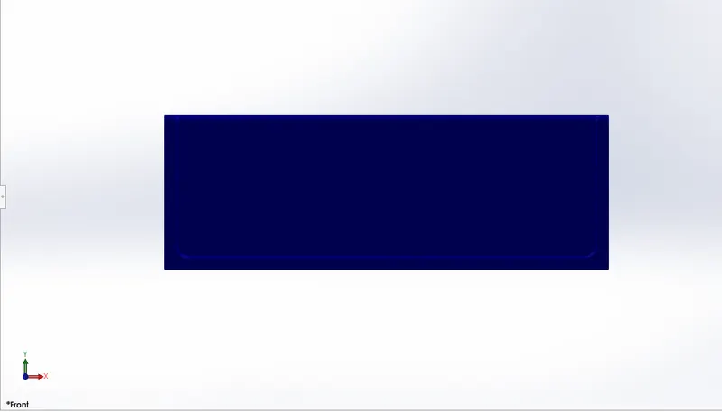
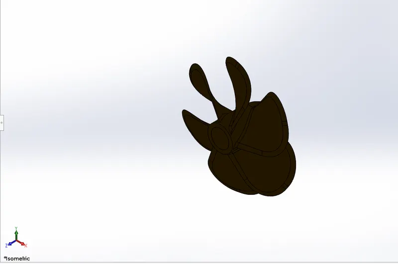
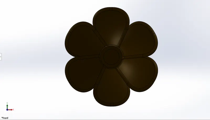
6.PROPELLERS:-These devices are with rotating hub and radiating blades that are set to a pitch to form a helical sprial,that,when rotated perform a action which is similar to Archimedes screw.For designing of propeller a closed half bullet like sketch was drawn using line and spline and then it was made to revolve like this it base is created and two rectangles are drawn in different planes and made to loft and circular pattern was performed.
Commands employed:-
- Sketch
- Revolve
- Refarance plane
- Loft surfaces
- Cut extrude
- Fillets
- Circular pattern
Some orientation of Propeller:-
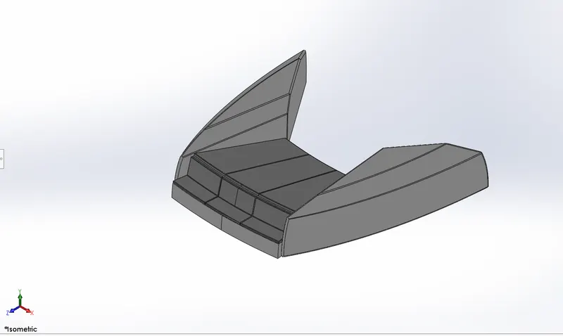
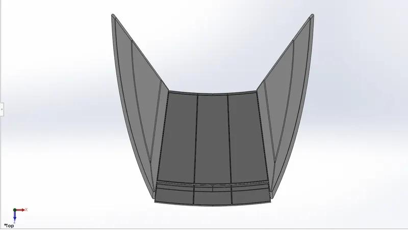
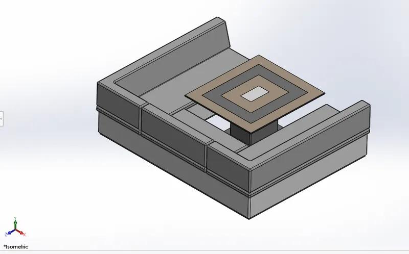
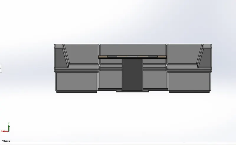
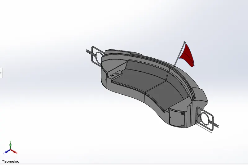
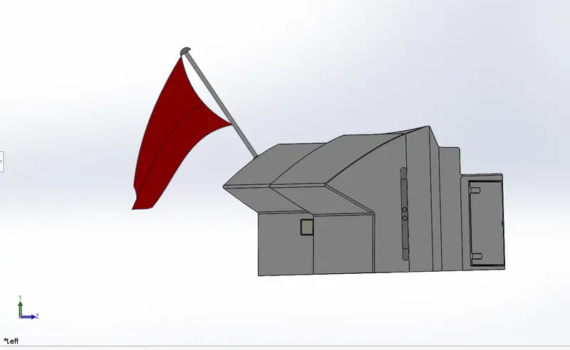
7.SEATS:-These are the seats which are designed for comfort.They all have been designed over hull surfaces which is called deck.These seats are part of luxury which can be enjoyed with the co-passengers.The front seat is place at front side of deck and middle seat and rear seat are palced behind superstructure.Middle seat also consist of dinning table which has been solid modeled.Rear seat has also a flag a as symbol of yacth and two steel door foor the stairs.
a.FRONT SEAT:-
Commands employed:-
- Sketch
- Referance plane
- Sweep surface
- Surface extrude
- Trim suraces
- Surface fill
- Lofted surface
- Cut extrude
- Fillets
- Chamfer
- Dome
- Mirror
Some orientation of front seat:-
b.MIDDLE SEAT:-
Feature employed:-
- Boss extrude
- Chamfer
- Fillets
- Mirror
- Referance plane
- Sketch
Some orientation of Middle seat:-
c.REAR SEAT:-
Feature employed:-
- Refarance plane
- Sweep surface
- Surface offset
- Surface extrude
- Ruled surface
- Surface extend
- Surface trim
- Surface Knit
- Lofted surface
- Boss extrude
- Chamfer
- Fillet
- Mirror
Some orientation of Rear seat:-
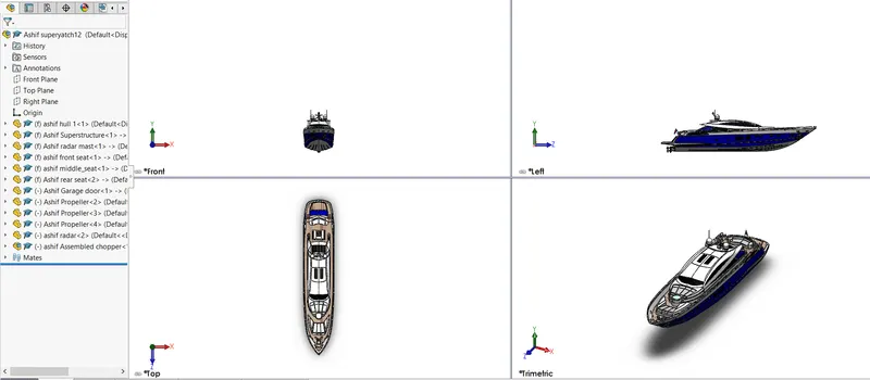
Assembly of yacth:-
- Open new file for assembly
- Import all the part by using insert component.
- Specially in this case as we have modelled many part on hull surface so we don't find any difficulty to fix the components such a superstructure and all seats
- Hull will get fixed automatically.
- By importing superstrcture and seats and by clicking ok they are fixed on hull automatically.
- Radar mast will get fixed on superstructure automatically as it was created on it's surface only.
- But their are some parts which are to be fixed by using mates like propeller,radar and garage door.
- All these 3 parts (propeller,radar,garage door)are mates using concentric mate and coincdent mate.
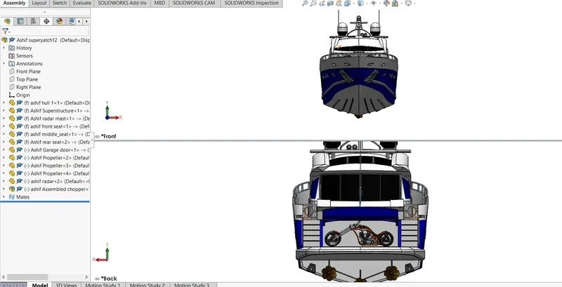
- After assembly of all the parts,american chopper was imported and fixed into garage.
Some orientation of assembled yacth:-
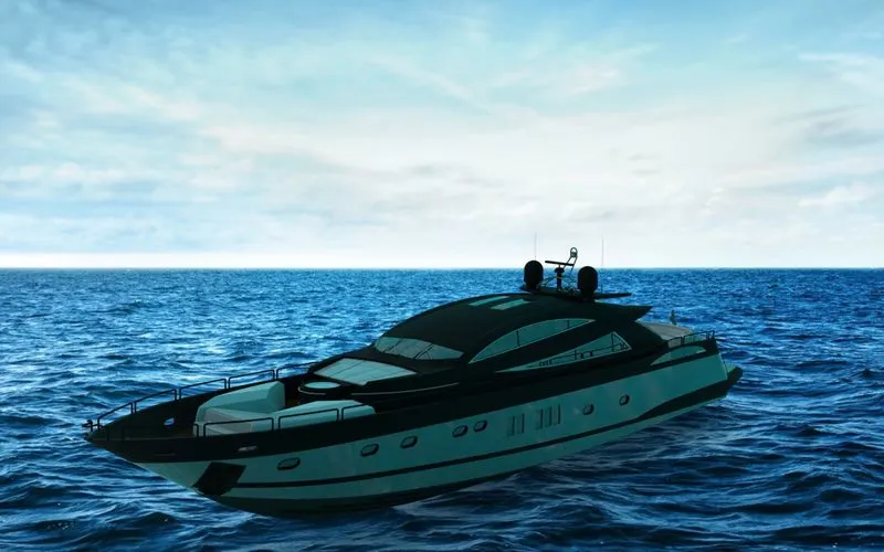
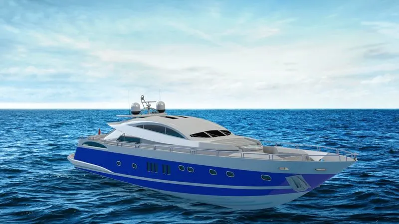
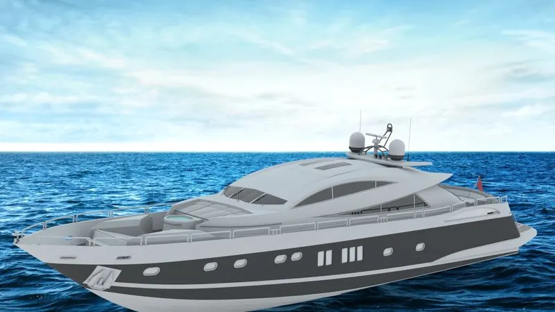
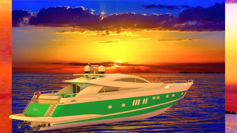
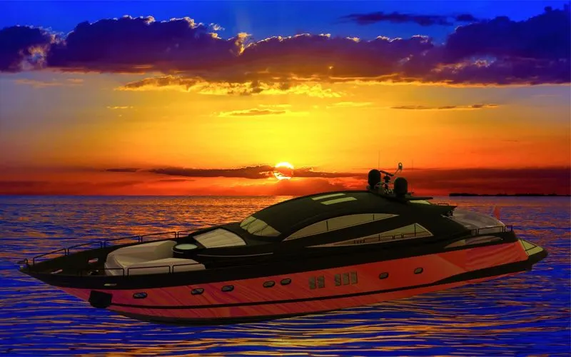
DETAILED IMAGE OF RENDERING OF SUNSEEKER YACTH:-
CONCULSION:-
The following project is done to understand the surface modelling tools of solidwork.This project teaches us how to use different tools of surface modelling.We also learn how to apply decals and appearance.We also learn how to render our 3-D model so that it looks as realistic as possible when it gets manufactured.
THANKYOU