Project - Switch Bezel Design
REPORT FOR SWITCH BEZEL
EXPLAINATION:-
TOOLING AXIS
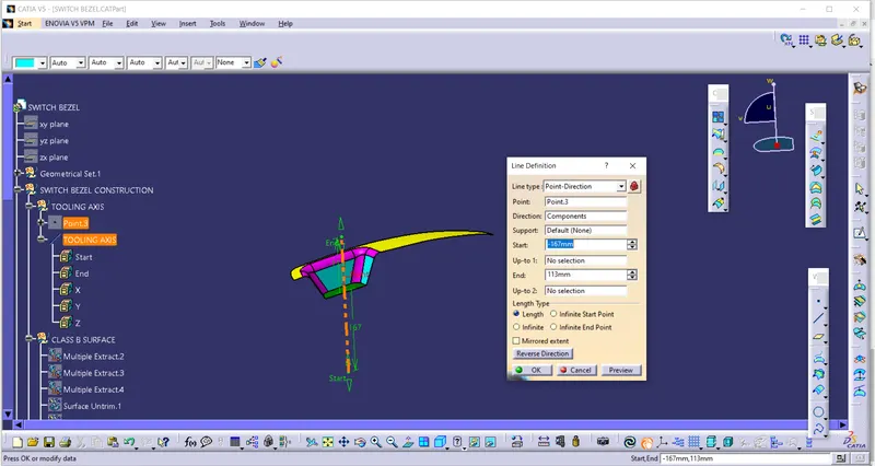
- In this plastic component tooling axis has been created by using compass method.
- Compass is brought to the surface and placed anywhere on the surface.
- Now by moving compass we check that all surface are gree or not.
- If so we lock the compass direction by right clicking on compass and use lock direction option.
- Now create point on surface and create a line using point-direction.
- Using point as referance and compass direction as direction.
- We get a line that is our tooling axis.
CREATION OF PLASTIC COMPONENT:-
- All the surfaces are extracted from class A surface.
- untrim all the surface and extrapolate them using point-continuty and curvature.
- Now offset the surface by thickness of 2.5mm which is the thickness of the component.
- Now trim the surface. Here we get class B surface.
- Now addition of fillets are done which is (14-2.5)mm.
- Now insert new geometrical set for class C surface and we take boundary of class A surface.
- Now we do sweep using drafting option taking tooling axis as direction and giving draft angle of 3degree.
- Now join class C and class A surface .
- And trim new join with class B surface.
- Here we get our plastic component.
- Insert new part body and open part workbench and convert plastic component into closed body.
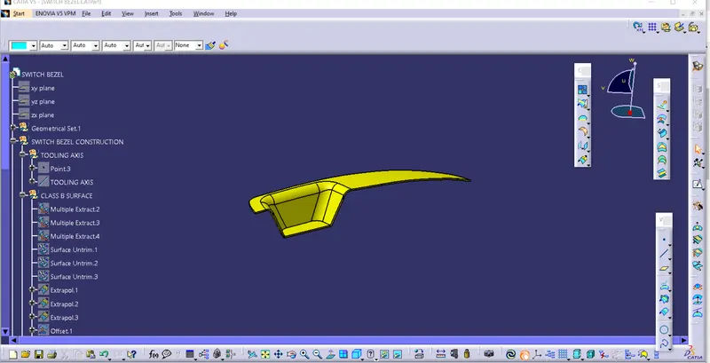
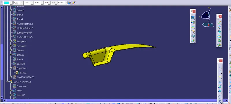
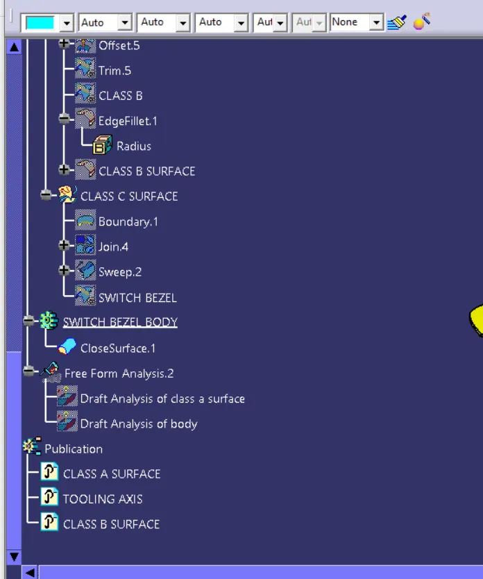
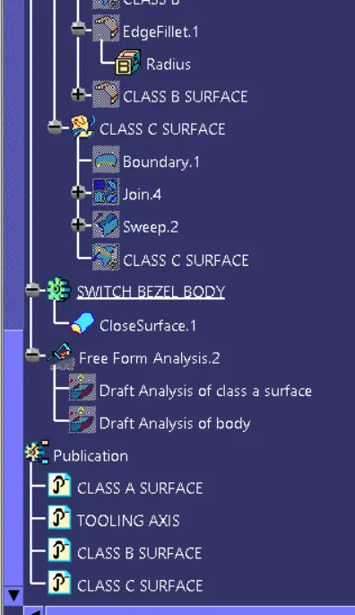
FEATURE TREE:-
PUBLICATION:-
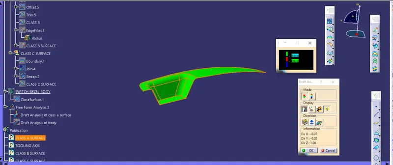
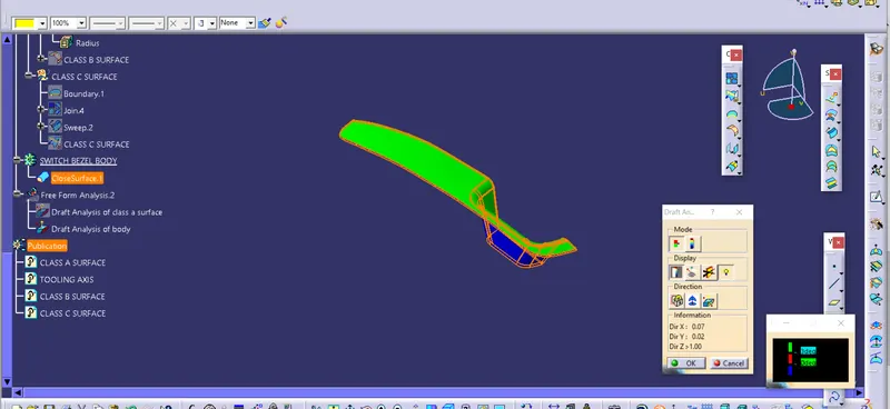
DRAFT ANALYSIS VIEW OF CLASS A SURFACE
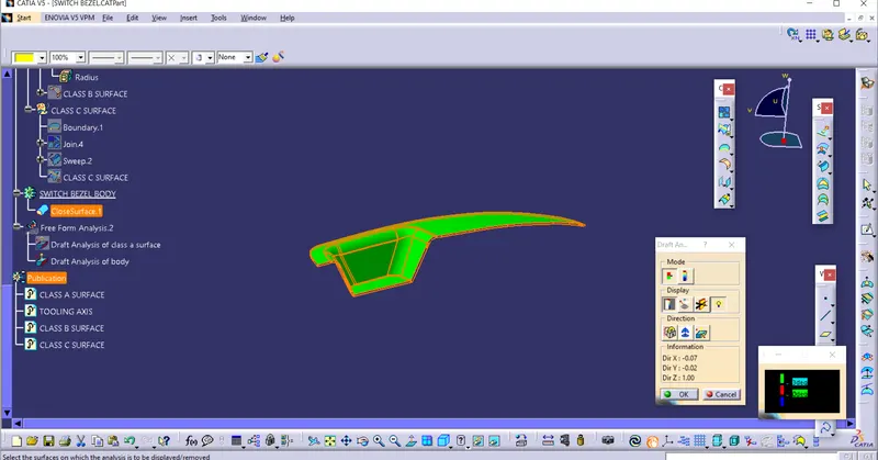
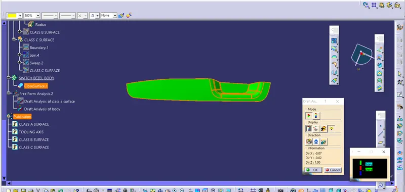
DRAFT ANALYSIS OF SWITCH BEZEL PART BODY
THANKYOU