Draft Analysis on a Fan Cover
OBJECTIVE:- CREATING TOOLING AXIS FOR FAN COVER AND PERFORMING DRAFT ANALYSIS
INTRODUCTION:-Draft analysis is performed because no component can be manufactured without giving draft.This is so beacuse if the ejecting surface of component is 90 degree from the base the component will cling with the mold which can cause unnecessary friction between the mold surafce and component and it may cause plastic defects.So, here comes the role of draft angle which helps the component in easy ejection from the mold. This helps us in getting good surface finish component and life of mold also increases. The draft is provided to core ,cavity and component. The nominal value of draft angle is 3 degree for plastic component.
COURSE OF ACTION PERFORMED FOR TOOLING AXIS :-
Step 1:- The very 1st step is to import Class A Surface to catia.
- open catia > file > select downloded class A Surface
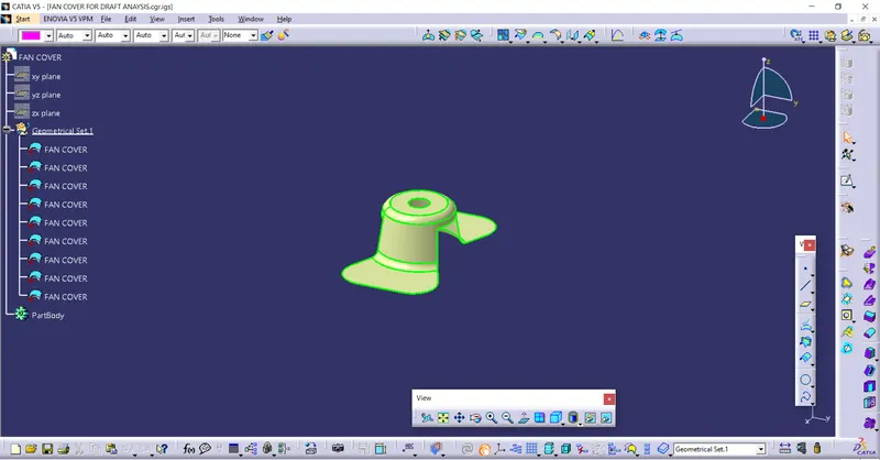
Step 2:- Ensuring that their sholud be no gap between any surfaces of Class A Surface.This step can be acheived by using join option or boundary option.
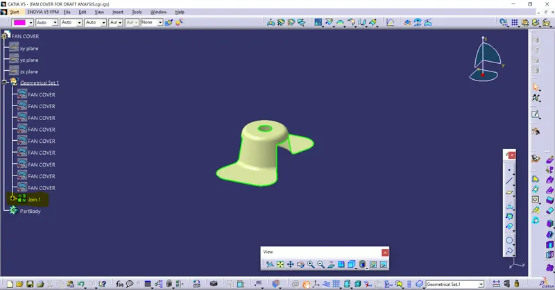
Step 3:-Find the tooling direction. Tooling axis is direction in which mold opens.
- By self visualising get rough idea that tooling axis could be in particular direction.Now create intersection between the Class A surface and ZX-plane.
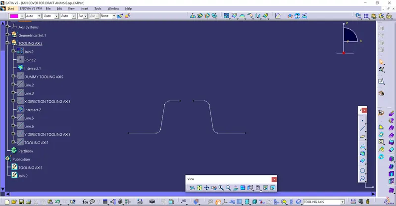
- After getting intersect , draw a dummy tooling axis.In the following case Z-Direction is the dummy tooling direction.Creation of dummy tooling axis is not compulsury, this step can be ignored.
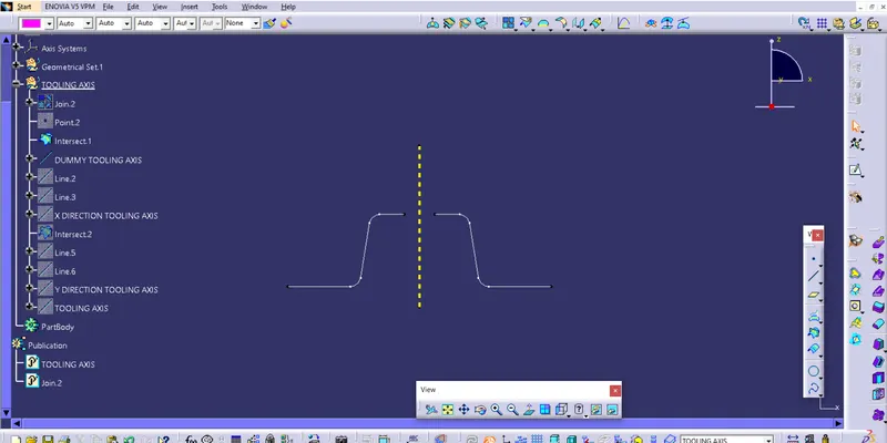
- Draw lines with the faces that is to be drafted on the both side and then create another bisecting line. Now line we got is tooling axis for that face, i.e X direction tooling axis.This method is called bisecting method. The yellow colour line is X diection tooling axis.
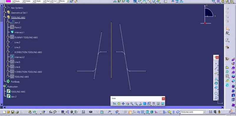
- Similarly, same procedure is followed for the another face and the bisecting line we get is tooling axis for that face ,i.e Y direction tooling axis.Now again we bisection the both x and Y tooling axis which will give us main TOOLING AXIS for the component.
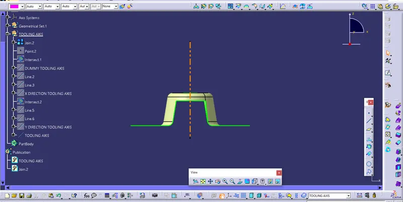
- Now we publish the TOOLING AXIS and Class A surface, so that it is easy to access.
FEATURE TREE OF TOOLING AXIS :-
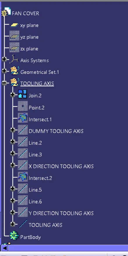
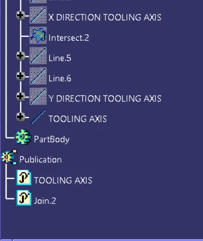
COURSE OF ACTION FOR DRAFT ANALYSIS:-
- Go to insert>Analysis>Feature draft analysis
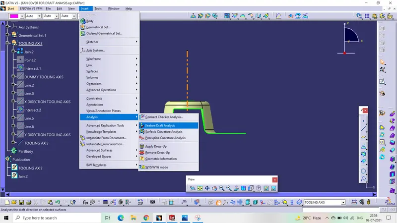
- Select the compass and place it on the tooling axis and lock the direction of compass using lock.
- Now select the surface and it will give the draft analysis of every face.
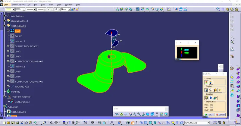
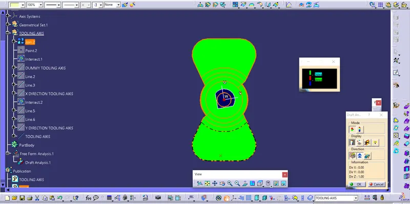
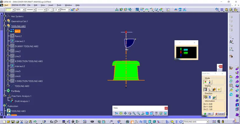
- Green colour shows that draft angle is 3 degree or more then 3degree which means that component can easly clear the mold.Where as red colour shows that draft angle is below o degree to 3 degree. And blue colour shows that draft angle is zero or negative.
- we can use Analysis under the running point to measure the degree of angle at every face of the component.
DIFFERENT ORIENTATION OD DRAFT ANALYSIS:-
ISOMETRIC VIEW
TOP VIEW
FRONT VIEW
THANKYOU