AMERICAN CHOPPER
TITLE OF THE PROJECT:- DESIGING AND MODELING OF AMERICAN CHOPPER
OBEJECTIVE:-Understanding and mastering the solidworks interface and implementing the features and sketch tools available in solidworks like convert entities,offset and many more,features like extruded bose,shell feature, split tool,projected curve , referance plane and many more. One the many objective of this project is to learn the Assembly of different parts and thier Rendering in solidworks visualize.
INTRODUCTION:- An American chopper is a type of modified (meaning "chopped") motorcycles which emerged in California in late 1950s.Characteristic feature of chopper are long front end with extended fork and frames without rear suspension with exotic looks and colours.
In this particular project,We will discuss how to model various parts of american chopper with their appearance and assembly of various parts together by usings mates.We will also learn how to apply decals and to add cameras for rendering.And then finally we will do rendering using solidworks visualize.
FLOW CHART:-
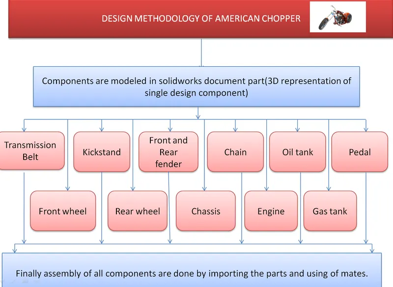
DESCRIPTION:-
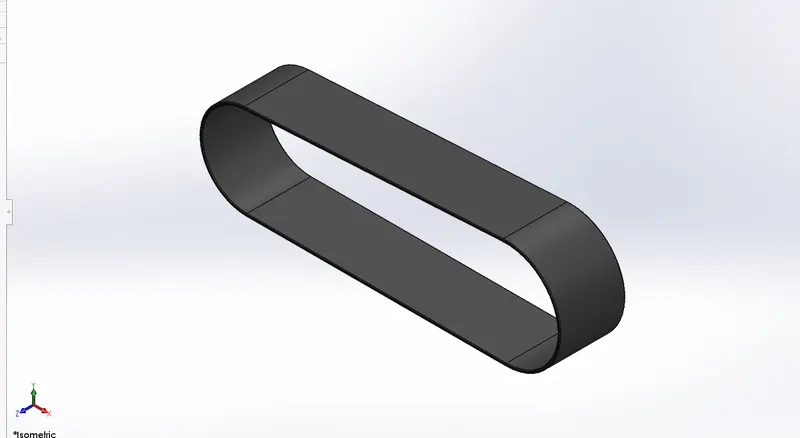
1. Transmission belt : It's loop of flexiable material made with mate rubber finish used to transfer power.It is used to link two rotating shaft.The following transmission belt has been mated with engine rotor to get assembled in the chopper.
Features Employed:-
1.Sketch
2.Offset entites
3.Extruded base
4.Fillets
FIGURE:- Transmission belt
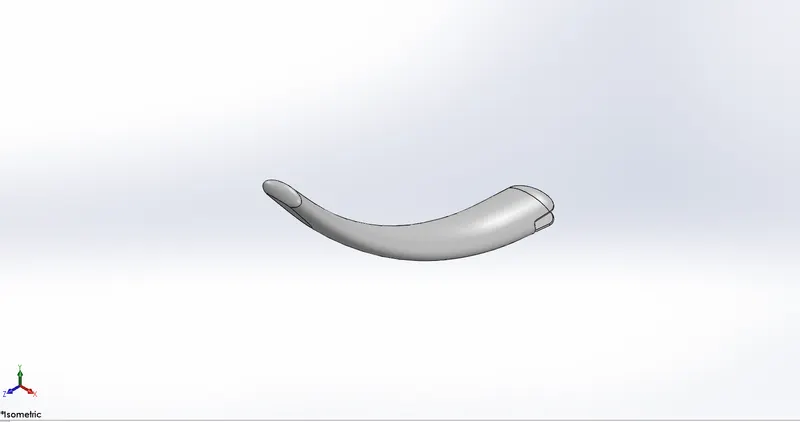
2.Kickstand:- A kickstand has been provided to chopper which is of chromium metal to kept upright.Kickstand is mated with chassis to get assembled in the chopper.
Feature Employed:
1.Sketch
2.Loft
3.Dome
4.Extrued cut
5.Split
6.Extrued base
7.Fillets
FIGURE:- Kickstand
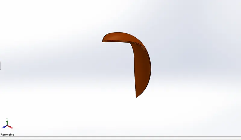
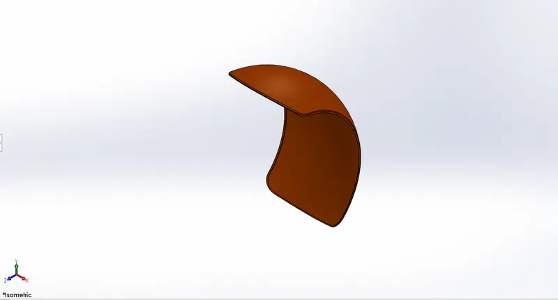
3. Front and Rear Fender:- Fenders are the frame that aviod mud, sand and many unwanted thing from being thrown into air by rotating wheel.They are assembled with wheel planes and chassis planes in the chopper.
Feature Employed:-
1.Sketch
2.Revolve base
3.Split
4.Fillets
5.Shell
FIGURE:- Front fender
Rear fender
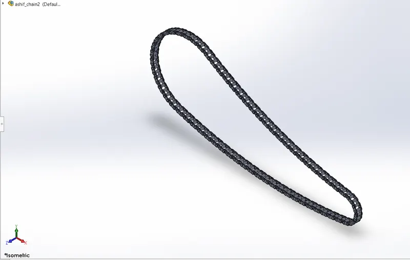
4.CHAIN:- Chain is used to transfer power to driving wheel.It is assembled in chopper using width mate with rear wheel and concentric mate with engine and rear wheel.
Feature empolyed:-
1.Sketch
2.Extrued bose
3.Fillets
4.Curve Pattern
5.Mirror
FIGURE:- Chian
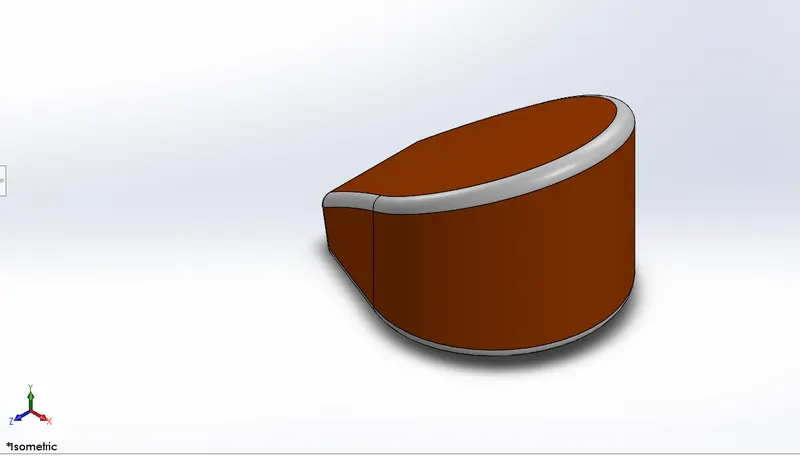
5.OIL TANK:-It is just hollow closed space to store oil required for the chopper.It is assembled with the chopper using coincident mate with engine and chasis planes.
Feature Employed:-
1.Sketch
2.Extruded bose
3.Fillets
4.Shell
5.Combine
FIGURE:- Oil tank
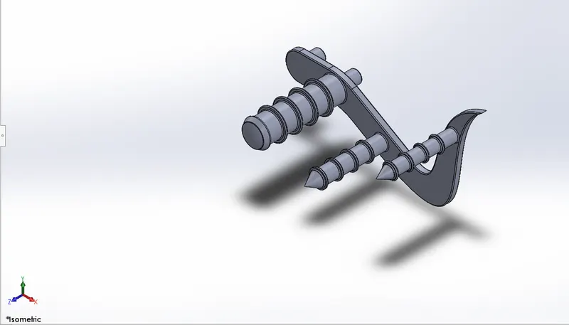
6.PEDAL:- Pedal is that part in chopper which help to hold foot and prevent from sliping and provide better transfer of power. It has been mated to chopper with the help of concentric mate with chassis planes.
Features Employed:-
1.Sketch
2.Extruded bose
3.Fillets
4.Dome
5.Chamfer
6.Linear pattern
7.Revolve
FIGURE:- Pedal
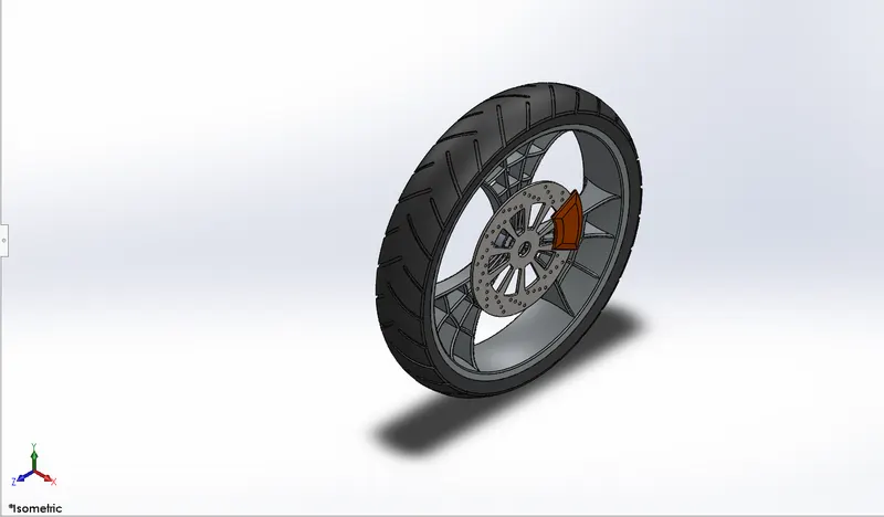
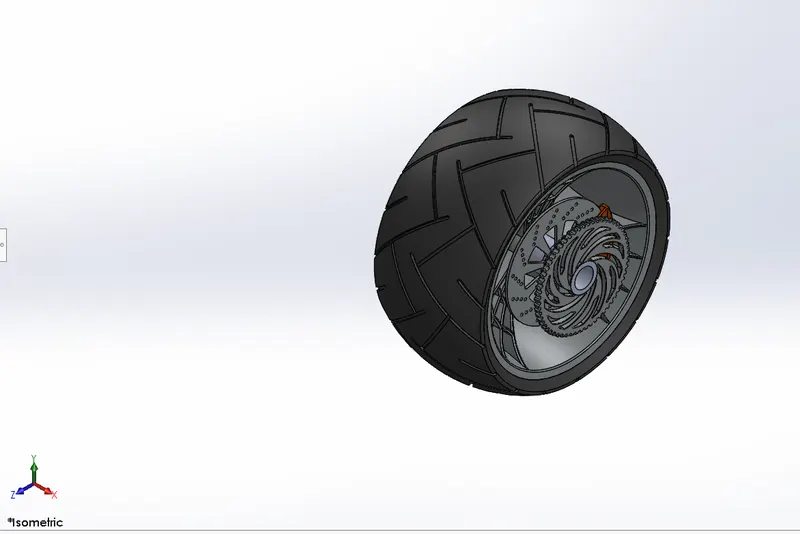
7.FRONT AND REAR WHEEL:- Front and Rear wheel itself contain main part like rim,caliper,rotor,tire and sprocket(only in rear wheel).Wheels are mated with the chassis using concentric(front wheel is mated with front fork and rear wheel is mated with chassis),parallel,coincident(Rear wheel is mated with chassis).
Features employed:-
1.Sketch
2.Extruded bose
3.Extruded cut
4.Circular pattern
5.Revolve
6.Revolve cut
7.Fillet
8.Chamfer
9.Combine
FIGURE:- Front wheel
Rear wheel
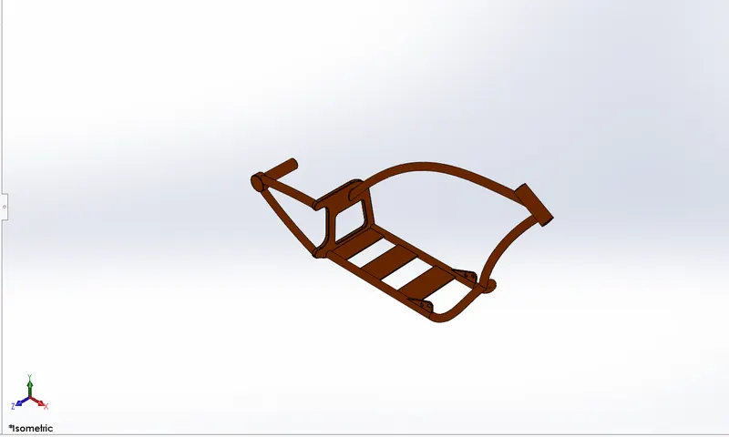
8.CHASSIS:- Chassis is a metal frame in which all parts are fixed.First it is brought into the plane and then all parts are brought and fixed by use of different mates with the plane of chassis. After applying all mates ,we use float to have a look that all parts are fixed or not.
Features Employed:-
1.Sketch
2.Extruded bose
3.Projected curve
4.Sweep
5.Dome
6.Referance plane
7.Split tool
8.Combine
9.Fillets
10.Mirror
11.Extruded cut
FIGURE:-Chassis
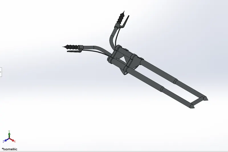
9.FRONT FORK:-Fork is that part which take majority weight of the body.Basically, In chopper we have drawn bike handle also and cable by use of projected curve.It is mated with the chassis plane using concentric,width and limitangle mate.And front front wheel and front fender is mated with front fork using various mates.
Features Employed:-
1.Sketch
2.Revolve
3.Extruded bose
4.Linear pattern
5.Dome
6.Fillets
7.Projected curve
8.Combine
9.Mirror
FIGURE:-Front fork
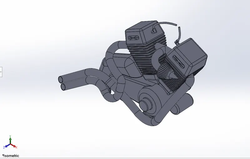
10.ENGINE:-Engine is that part of chopper where combustion take place and work for moving of chopper is done.Some important feature have been used in making of engine like making of composite curve with projected curve for exhaust .It is the second component of chopper the is assembled with chassing using coincident mate and also by giving some offset.
Feature Employed:-
1.Sketch
2.Boss-extrude
3.Fillets
4.Revolve
5.Referance plane
6.Circular pattern
7.Chamfer
8.Linear pattern
9.Dome
10.Split
11.Dome
12.Mirror
13.Sweep
FIGURE:-Engine
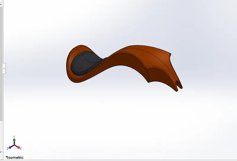
11.GAS TANK:-Gas tank is that part of chopper where fuel is stored in for the chopper.All the above parts/models have been modeled by use of solid modeling but this gas tank had been modeled by using surface modeling because it is complex model.Features like surface loft and surface extrude had been used for gas tank and use of projected curve had been also done. It is mated with chassis by using distance and coincident mates.
Features Employed:-
1.Sketch
2.Surface sweep
3.Surface trim
4.Surface boundary
5.Mirror
6.Surface knit
7.Surface loft
8.Split
9.Shell
10.Fillets
FIGURE:-Gas tank
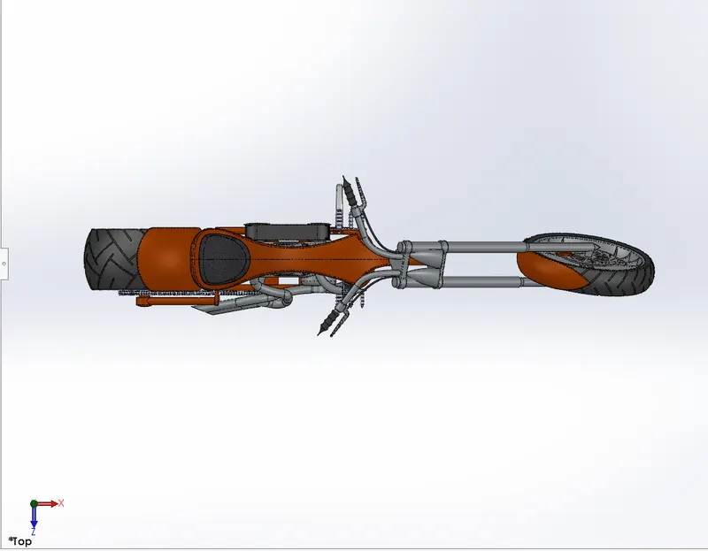
SOME VIEW OF ASSEMBLED AMERICAN CHOPPER:-All model are imported in assembly file and then assembled by using different mates.
a.Isometric view
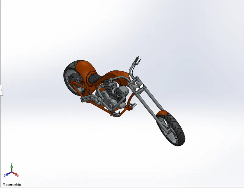
b.Front view
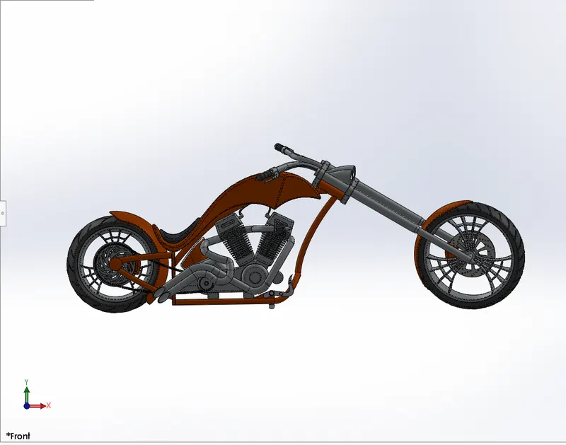
c.Side view
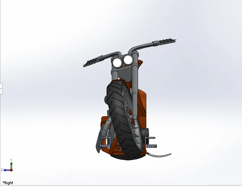
d.Top view
DETAILED RENDERING IMAGES OF AMERICAN CHOPPER:-
1. Appearance:-Metallic Lipstick Red
scene:-Tokyo atrium
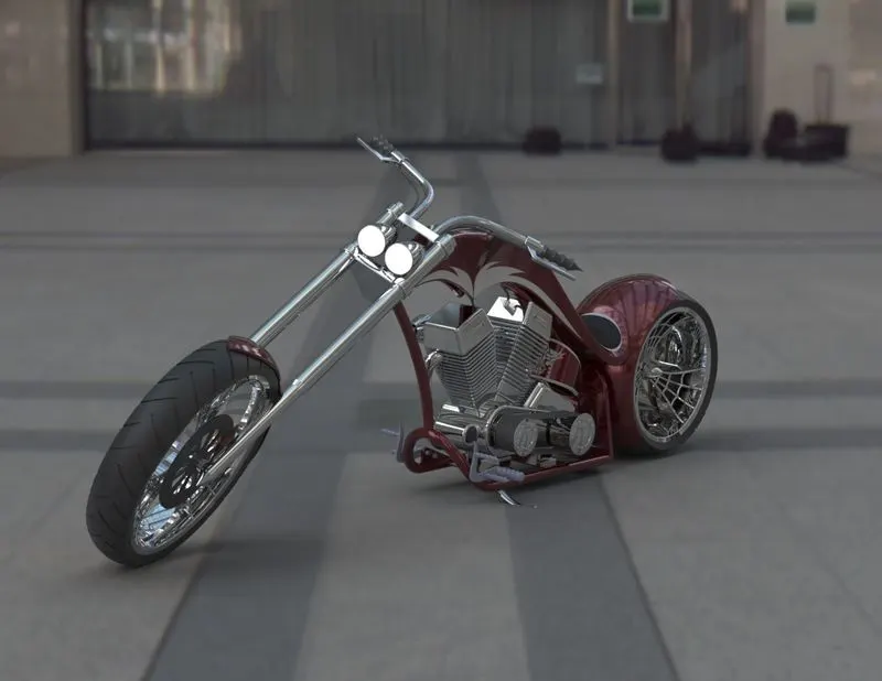
2. Appearance:- Metallic Lipstick Red
scene:-Warehouse
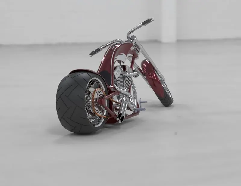
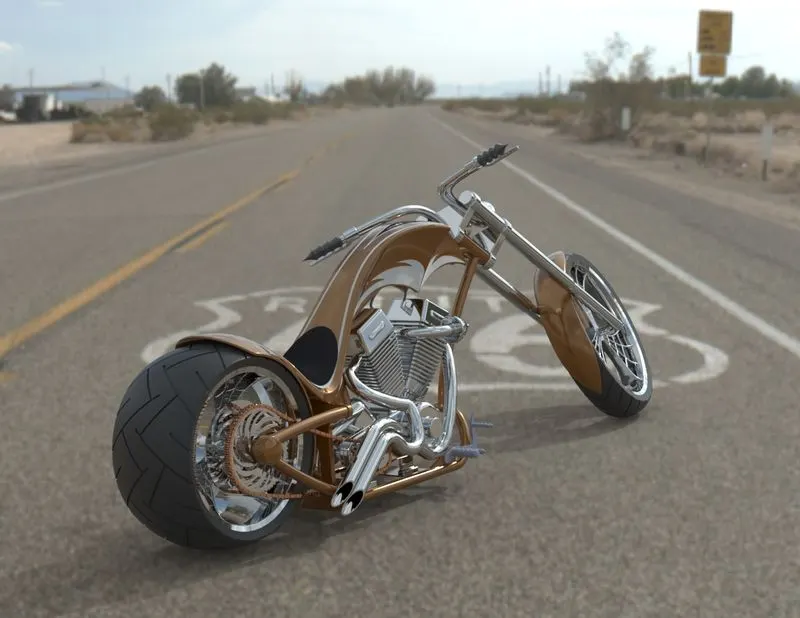
3. Appearance:-Metallic Sandune
scene:-Route66
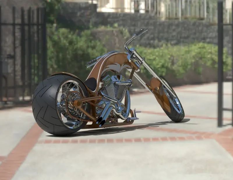
4. Appearance:-Metallic Sandune
scene:-Sunny driveway
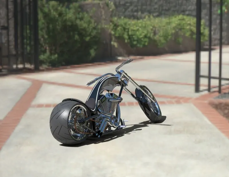
5. Appearance:- Metallic black moon
scene:-Sunny driveway
CONCLUSION:-
The following project is done to understand the GUI of solidworks,photoview360 and solidwork visualize.This project teaches us that how to use planes and variuos tools in solidwork.In assembly of variour parts we get to learn how to use mates.In photoview360 we get to learn how to apply appperance and decals in perspective view and we also learn setup of camera.After completing all the above proces,we move for rendering in solidwork visualize .Here we learn to apply scene and apperance and after final rendering we get the final desired prototype which will almost look real when after bike gets manufactured.
LINK TO VIEW MODEL:-
a.Link for Assembled Chopper
https://drive.google.com/file/d/1Mn0gVy7BrALcyn-xKBlW3hWilLvjD7vA/view?usp=sharing
b.Link for American Chopper Render
https://drive.google.com/file/d/1gh8vAW-hGtn5fXU1sRI0iVrX1DW3H_EV/view?usp=sharing
THANKYOU