Week 9 - Project - Master Section Development
AIM:
To create the master section for the given class A surface along with the required engineering features.
OBJECTIVE:
The given class A surface into a component with the given engineering features from the given master section with the standards and perform the draft analysis on the component for the feasibility of manufacturing.
SOFTWARE USED:
Catia V5
CLASS A SURFACE ANALYSIS:
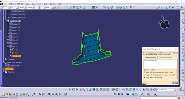
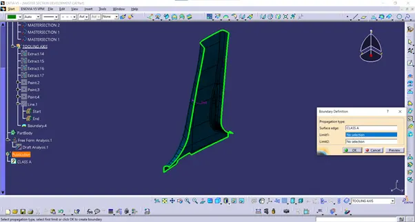
Initially, the given class A is inspected visually and also with the boundary commands to ensure the surface continuity and to avoid the irregularities or patches in the surfaces.
As we can see here there is slight discontinuity in the surfaces, this is fixed by increasing the merging distance to 0.002mm since the maximum limit is 0.003m,
TOOLING AXIS:
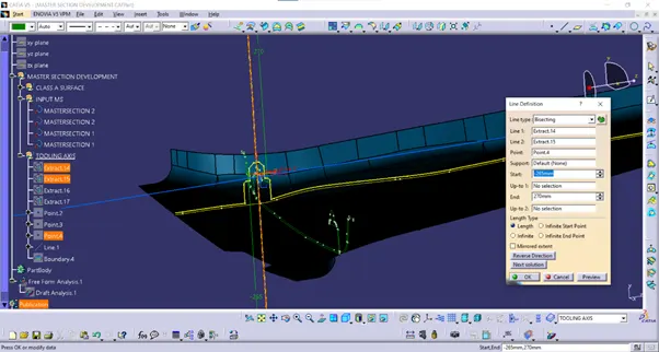
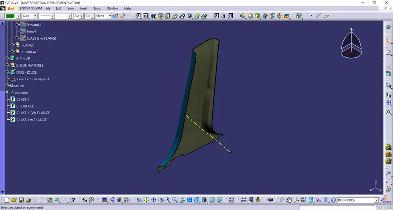
Then the tooling direction of the component is created in the surface class A itself. For this purpose, we are adopting the bisecting method, where the surface bisection line is the tooling direction.
As we are aware, the engineering features will clear the main tooling direction else while the side core axis.
Therefore, we are creating a bisecting line along the B side features from the master section, which is the tooling direction.
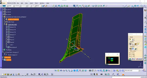
Draft analysis when carried out using the compass method, clears out the surfaces along the tooling direction with the draft angle of 3 degree.
SURFACE MODELING:
B SURFACE:
In developing the B surface rather than the conventional extract and trimming method we are directly making an offset to the thickness of the surface because the class A contains styling fillets over it and they are pretty much difficult and complex to get trimmed together.
FLANGE CREATION:
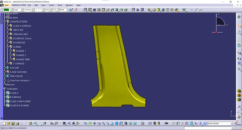
From the master section we can observe the two edge surfaces have a flange protruding outside the class A, this has to be created earlier as they are a part of the surface component.
Initially, the edges and the surface containing these edges are extracted using multiple extract separately,
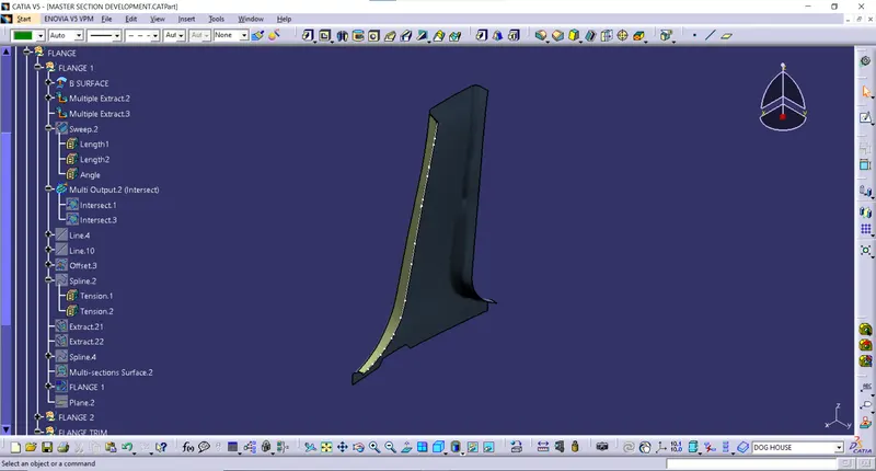
Then using the sweep command the surfaces are swept perpendicular, in the direction of the flange in the master section. After which the the swept surface is given offset to the surface and extended along the other side for intersection with class A.
The same procedure is carried out for the other side flange too.
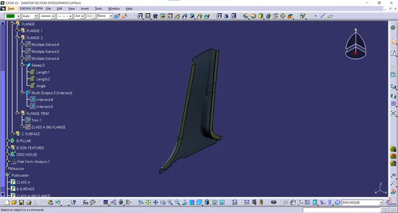
Then they are trimmed together with the class A surface.
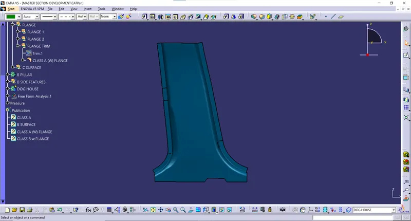
The same is again carried out for the B surface.
C SURFACE CREATION:
As usual, the surface edges along the class A are extracted using multiple extract and then they are swept along the tooling direction.
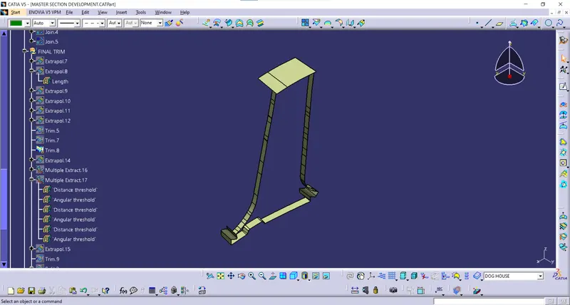
Then, the swept surfaces are trimmed along with the A surface after extrpolating till the intersection.
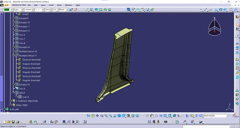
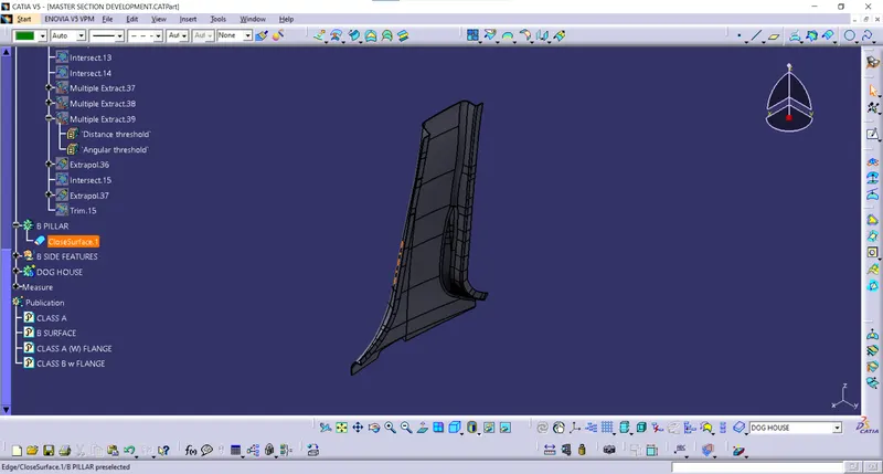
Once trimming together, the part model is created by giving the closed surface command.
ENGINEERING FEATURES:
Now, on the B side the engineering features are created. These are already described on the master section. Intrepret the feature and need to develop them.
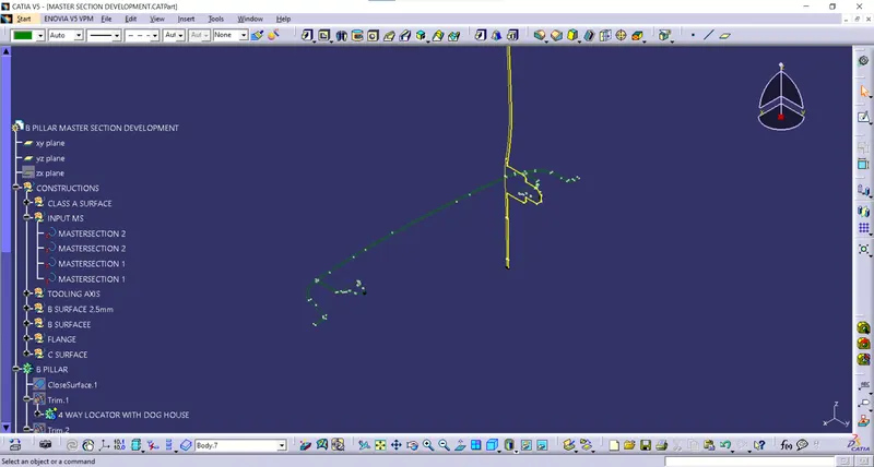
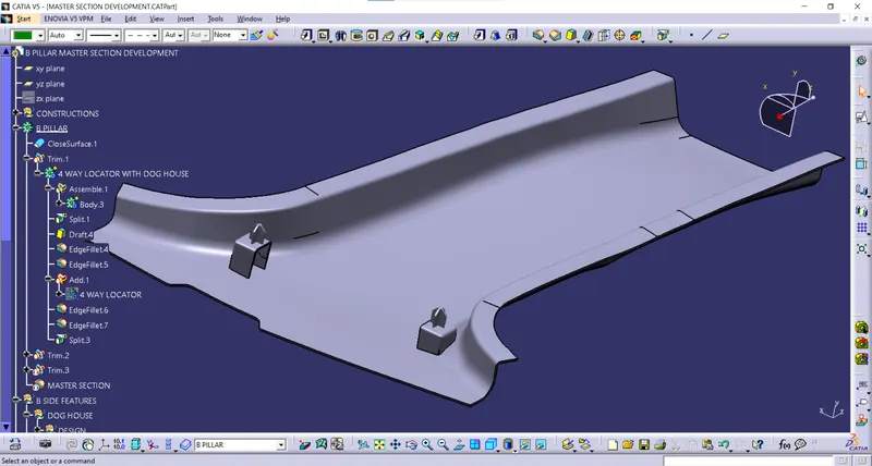
The given master section from which the features are developed. Interpreting the section we can conclude there is a 4 way locator for which a dog house is needed for the height factor. Thus the 4 way locator is mounted on the dog house and the flanges are designed earlier with reference to this section.
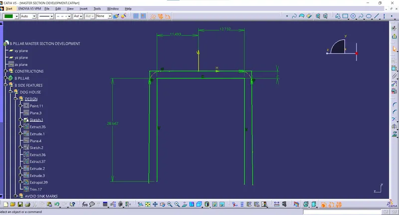
The design for the dog house sketch is created at first. Then this is extruded along the plane surface and then trimmed with the dimension surface.
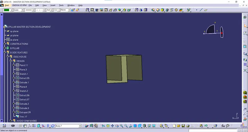
After the surface trimmed with extracted surafces along the section, they are turned into part body by thickening the component with its design standards.
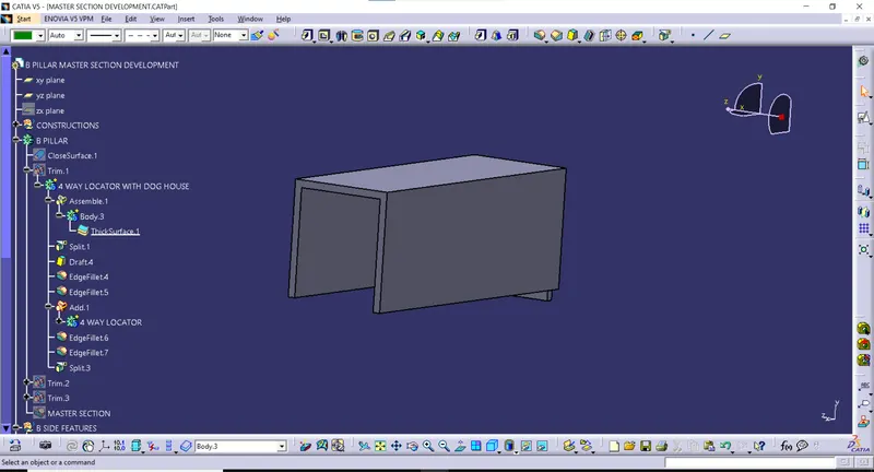
On top of the dog house is the 4 way locator which should be positioned and located. The sketch for the 4 way locator is shown below.
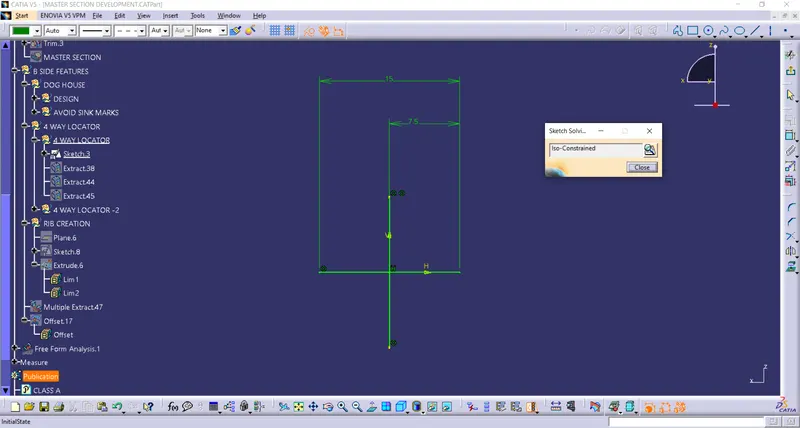
They are then padded along the perpendicular axis.
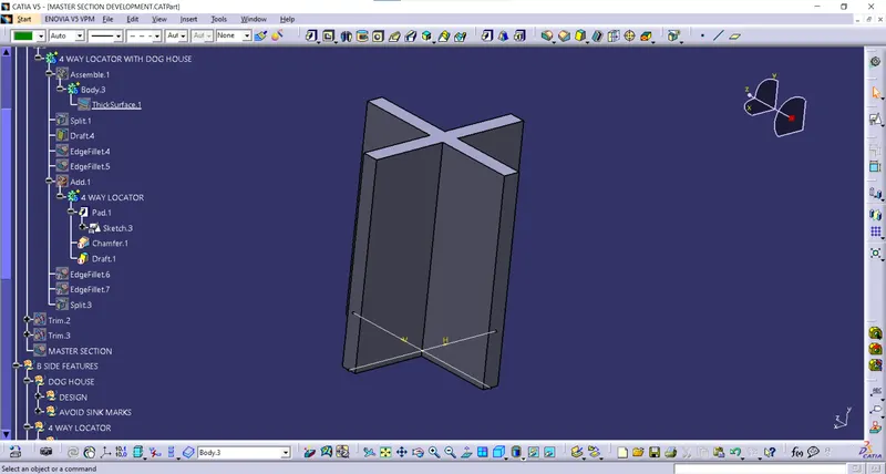
Then they are given chamfer and fillet defintion, once then the padded surface is assembled onto the doghouse.
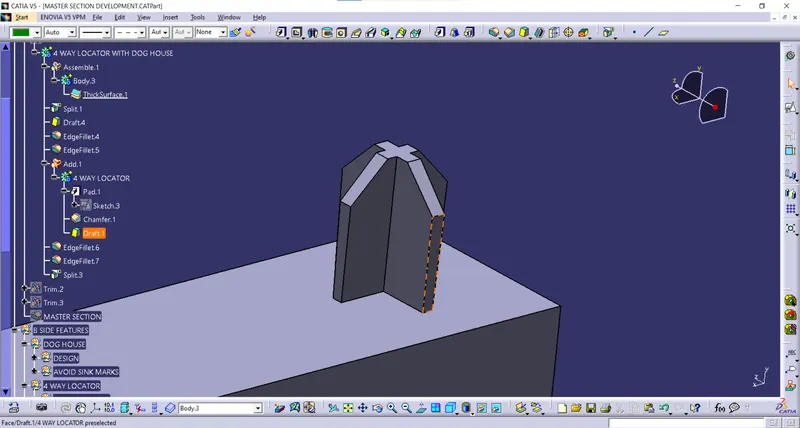
Then the dog house along with the 4 way locator is assembled with the main component.
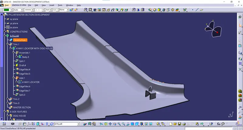
Then the same component is made onto the respective other side of the component.
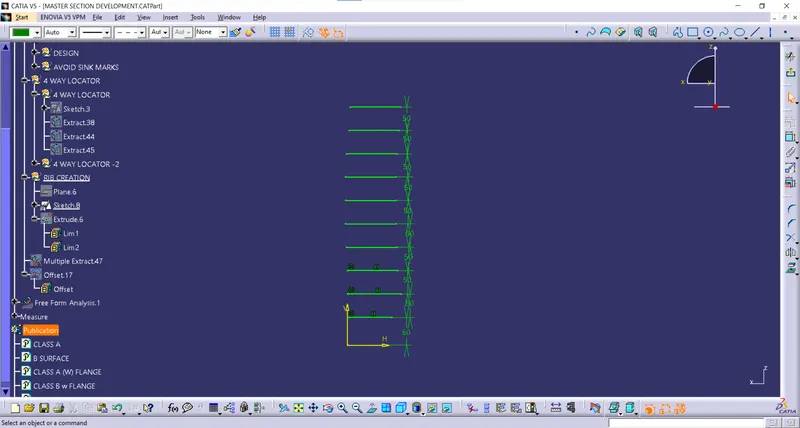
Then, the ribs are created with the a 50mm gap between them. The sketch creation for the ribs is shown below in the image.
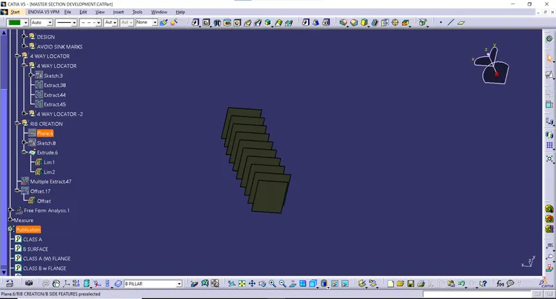
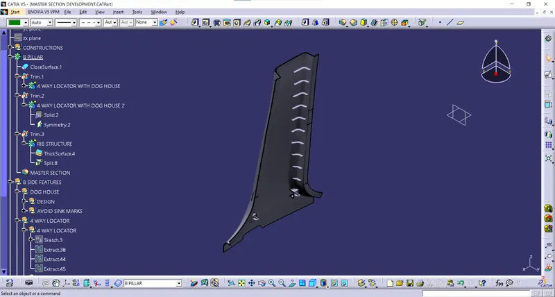
They are then extruded along the plane direction and then thickened with the draft and design rules for the rib and then they are splitted with the surface of the class A to determine the height of the rib. And finally they are union trimmed to the main component.
DRAFT ANALYSIS:
Then the draft analysis for the final component is carried out. This will ensure the component getting cleared in the tooling direction which inturn will ensure the manufacturing or mould feasibility.
The draft analysis for the component along the main toolinig direction is getting cleared out.
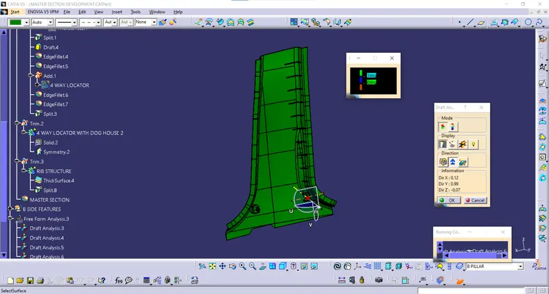
B side features:
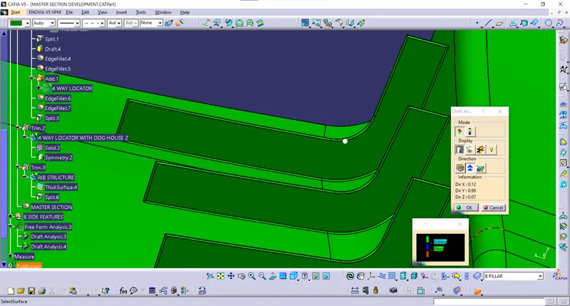
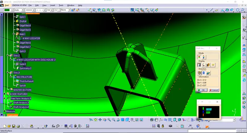
FINAL COMPONENT:
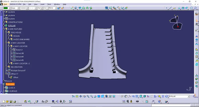
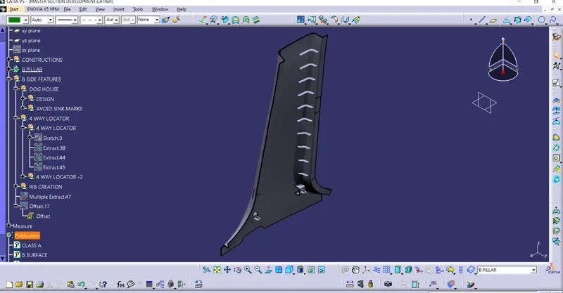
TREE STRUCTURE:
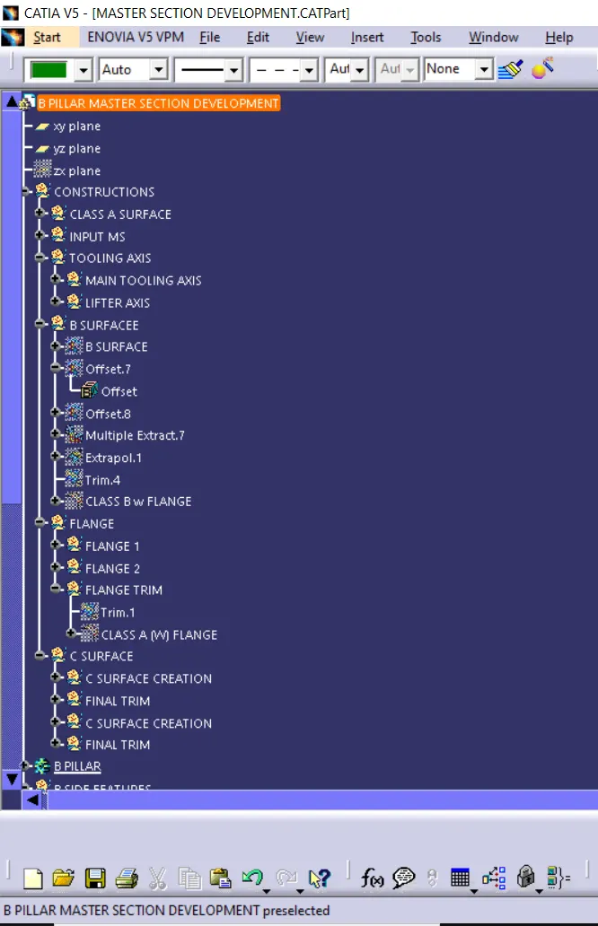
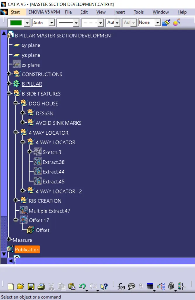
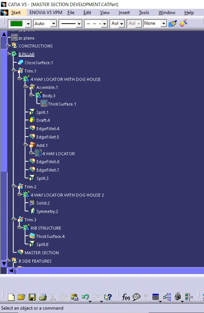
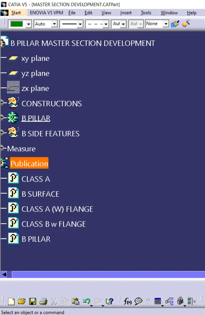
The geometry tree structure for the construction elements is given below,