Week 8 - Challenge 1 - Draft Analysis on a Fan Cover
AIM:
To create a tooling axis for a component and perform the draft analysis along the tooling direction
OBJECTIVE:
Ensuring the feasiblitiy of manufacturing procedure without any frictional damage, wear rate to the component by creating a centre tooling axis and adding draft angles for smooth ejection.
SOFTWARE USED: Catia V5
DRAFT ANALYSIS:
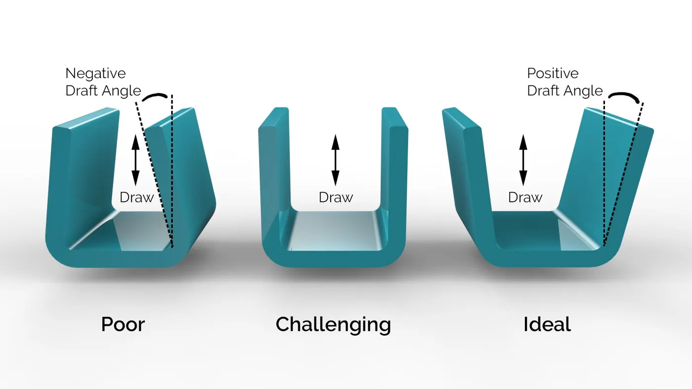
To allow the part to eject from the mould easily a draft angle must be added to all vertical walls. This reduces wear on the tool and reduces the possibility of drag marks on the surface of the part.
- A good rule of thumb is 1 degree of draft for every 25mm of cavity depth.
- Ideally with a minimum of 2 degrees.
- Also, the draft may need to be increased if you want a more textured surface finish.
PARAMETERS INVOLVED:
Pull Direction
Use to define the pull direction.
X Axis: If the object is aligned with the world coordinate system, the mold will be pulled away from the right side of the object.
Y Axis: If the object is aligned with the world coordinate system, the mold will be pulled away from the back side of the object.
Z Axis: This is the default. If the object is aligned with the world coordinate system, the mold will be pulled away from the top side of the object.
Custom: Allows you to define an alternative pull direction by clicking and dragging the Direction and Origin handles in the modeling views.
Draft Regions
Use to change the legend colors and define the tolerance values for sufficient and insufficient draft.
Positive Draft: Refers to a region where sufficient draft has been detected, in the same direction as the current pull direction. By default, these regions appear green, but you can change the legend color using the color palette.
Draft Angle (°): Use to define the tolerance value for sufficient draft. The default value is 1°. Select a value that is greater than or equal to 0°; it must also be greater than or equal to the Warning Angle.
Requires Draft: Refers to a region where insufficient draft has been detected. By default, these regions appear yellow, but you can change the color using the color palette.
Warning Angle (°): Use to define the tolerance value for insufficient draft. The default value is 0°. It must be less than or equal to the Draft Angle.
Negative Draft: Refers to a region where sufficient draft has been detected, in the direction opposite to the current pull direction. By default, these regions appear red, but you can change the color using the color palette.
COMPONENT:
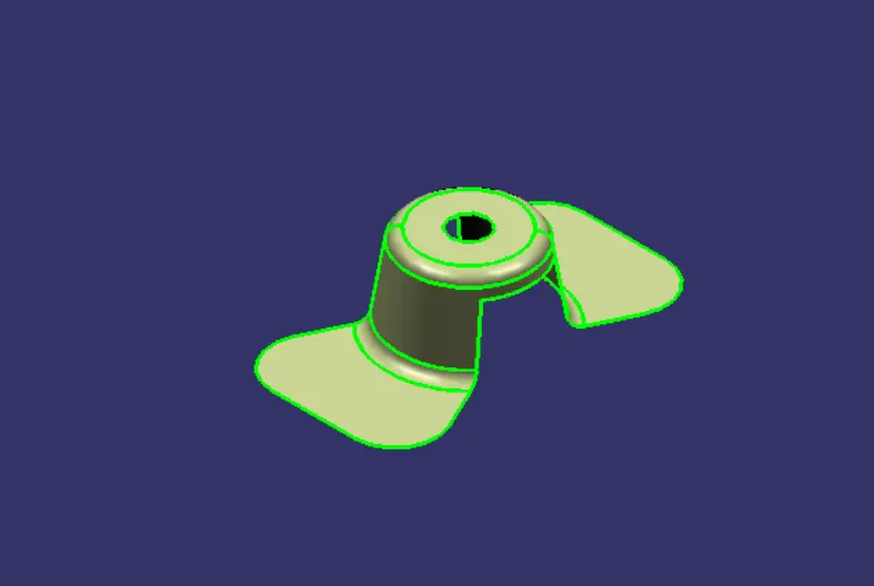
A typical cover for a fan housing. In order to ensure the manufacturability from a design perspective would be to make sure the component doesn't require extra facilitations like side core, side cavity etc. Also the component has to be ejected from the core and cavity without getting clustered onto the core and cavity part during the application of heat. This can be avoided conventionally by avoiding parallel surfaces to the tooling direction or vice versa.
DRAFT ANALYSIS:
In order to start the analysis some pre requisites are to be carried out in confirming continuity and connexity of the class A surface. They are as follows:
EXAMINING CLASS A SURFACE:
Initially, the class A surface has to be examined for its continuity and the surface has to be without and gaps and cutting portions. This can either be visually inspected or also can be carried out by using Join and Boundary conditions
JOIN: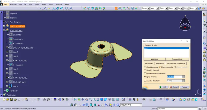
BOUNDARY CONDITION:
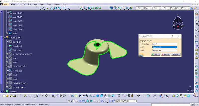
CREATING THE TOOLING AXIS:
Once the initial conditions are carried out then the tooling axis can be created. This can be carried out in two ways as shown below.
1. XYZ Intercept:
This method involves creating a dummy tooling axis for reference purpose and then inetersecting the profile of the component along the yz, zx, xy planes respectively.
Now, Create the dummy tooling axis by creating a point at the centre of the circle and creating a line along the Z-direction.
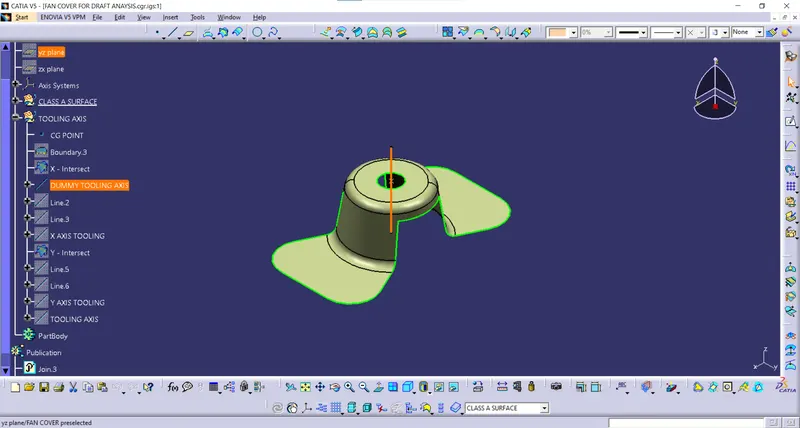
Then for the tooling axis creation the steps are as follows:
S1: Intersect the ZX plane with the class A surface and a profile of the surface will be formed.
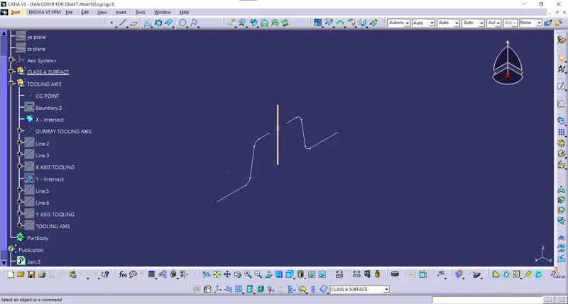
S2: Create lines along the portions of the profile that are mere parallel or parallel to the dummy tooling axis.
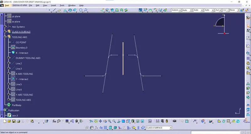
S3:
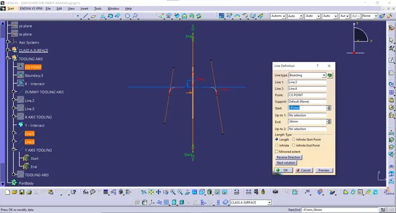
Now create a bisecting line along the CG point and the two lines created above and ensure the line propogating direction
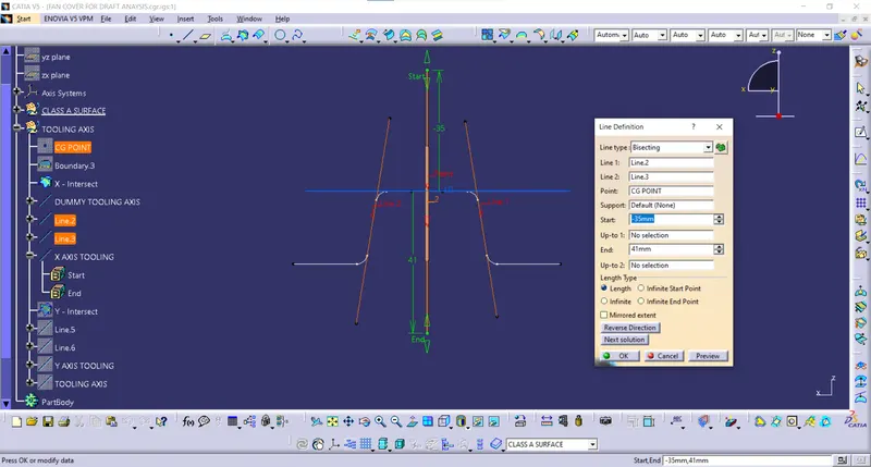
This intercept by the bisecting line will give the tooling clearance for the X-axis.
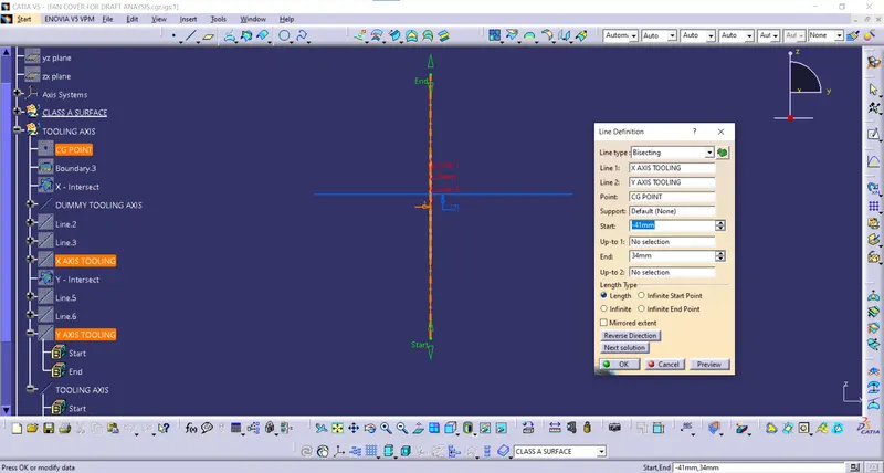
Then the same procedure is carried out along the Y-direction:
S1: Intersection of YZ plane and profile
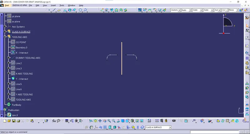
S2: Lines along the parallel curves.
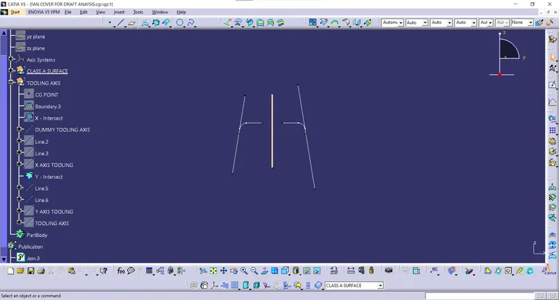
S3: Bisecting line
XY INTERSECT:
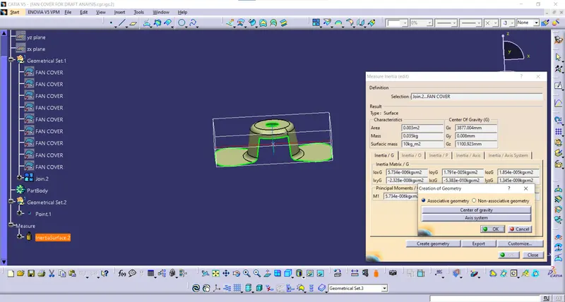
There can also be another method carried out by letting the inertia calculation carried out to find out the centre of gravity point and creating the tooling axis geometry.
DRAFT ANALYSIS:
Intially place the compass onto the component or the class A surface to be analysed.
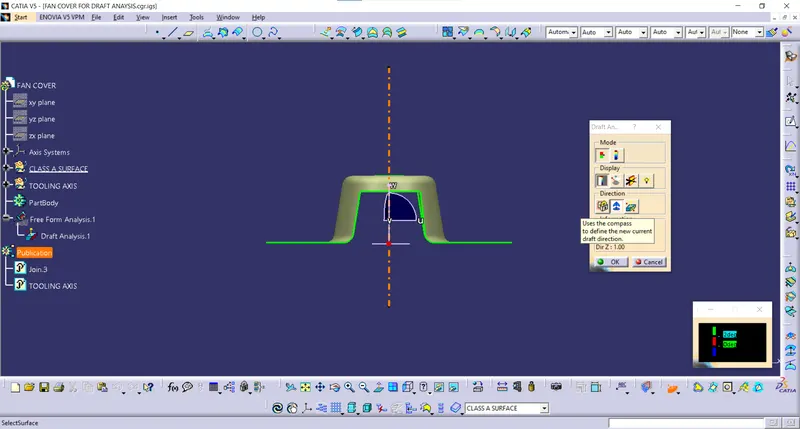
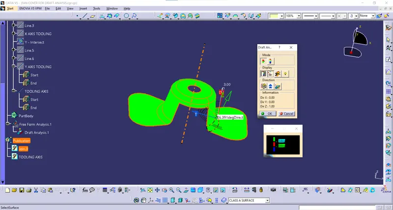
Locking the draft direction and then selecting the surface
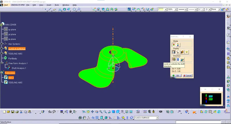
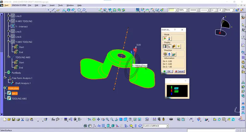
Changing the desired draft angle value and analysing the angle at each section or segment of the surface with the help of the draft analysis window
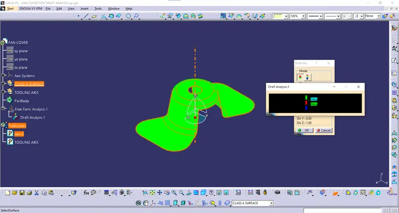
A more detailed analysis can also be carried out
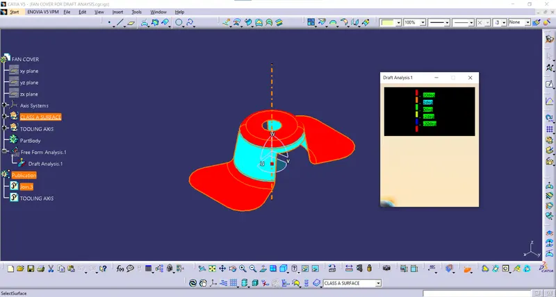
Here, a 3 degree draft angle is provided as the component has be molded. Generally, 7 degree is drafted for sheet metal components and 3 degree is sufficient for plastic components. And, ideally 0.5 deg of draft along the inside profile.
Final view of the drafted surface
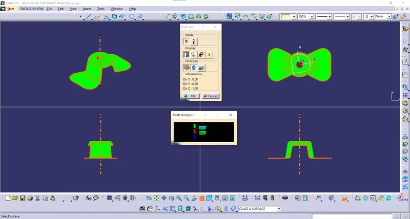
Since after drafted we can see there is no red or blue shaded regions which depicts the surface is not given enough draft, we can conclude the final draft for the surface.
The draft angle at a specified point can also be checked in the draft tool set.