Week 9 - Project - A pillar Design with Master Section
A PILLAR DESIGN WITH MASTER SECTIONS
OBEJECTIVE:
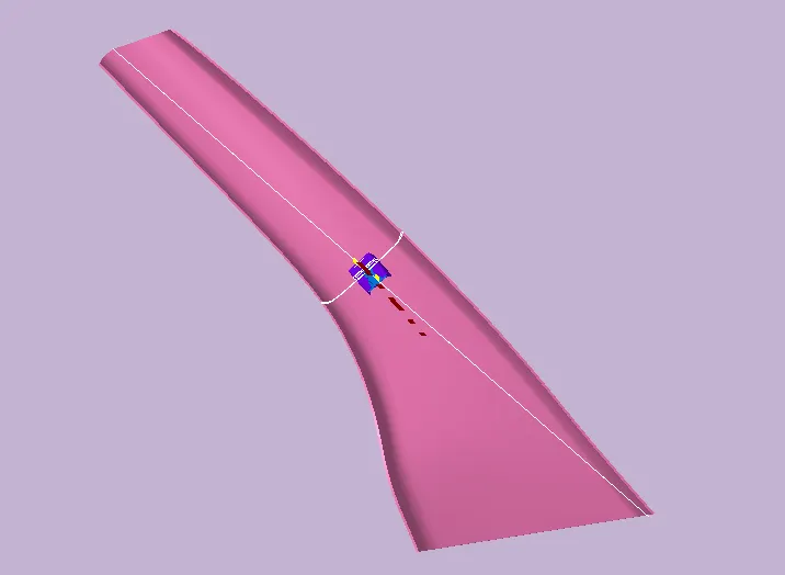
To Create the A-Pillar plastic Component from the given Master section with respect to the Class-A surface.To Create the appropriate tooling axis for the given Class-A Surface & Attachments meeting the requirements of the draft angle.To Attach B side Features in the component. And also to perform the Draft analysis on the model.
GIVEN:
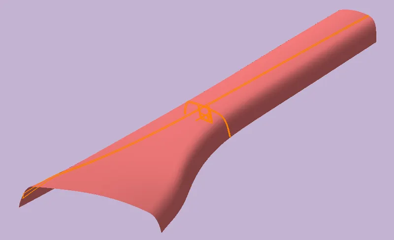
Thus the following as the Input of this components Class-A Surface with the Master sections.
INPUT:
Thus the given Class-A as my Input working surface & the thickness of the following component becomes 2.5 mm measured from the Master section and also the Edge fillet radius of Dog house 1.5 mm to be measured.
TOOL USED: CATIA V5
STAGE_1: TOOLING AXIS CREATION
The Tooling Direction which one is the direction that the mold pulls apart. The mold is built in two separate halfes of like Cavity side and the Core side. The Core pulls out from the Cavity along with the certain direction which is called as Tooling direction or Tooling Axis.
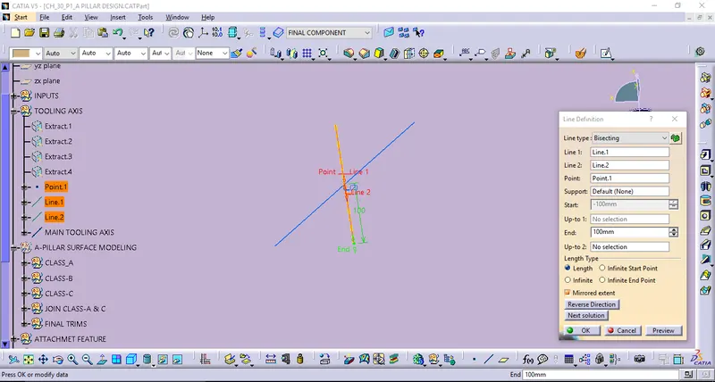
From this given Class-A surface and the Master section let us consider this to prefer bisecting method to create tooling axis . So that, here I create the tooling axis as followed from the master sections along with the dog house side wall section lines by working out the bisecting method on it then following Main toolin axis becomes obtained.
STAGE_2: DRAFT ANALYSIS FOR CLASS-A
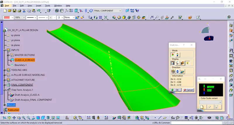
By using of Feature Draft Analysis with the Minimum draft angle of 3 deg along with the above Main tooling axis. Thus the results shown here as following as,
STAGE_3: SURFACE MODELING
STEP_1: CLASS-B SURFACE CREATION
Class-B surface, In which can be easily defined as the thickness of the part and it is not visible which is inside surface of the Class-A. For the following plastic component thickness as 2.5 mm from the Input data. While offseting Class -A for 2.5 mm of thickness directly by applying Offset surface definition And then we B-side of the following one which have some of its patch holes/no surfaces obtained over there. Then the patchs will be created into simplified surfaces to be obtain the complex one which Class-B surace. And the following solvings are,
By using of offset surface definition.
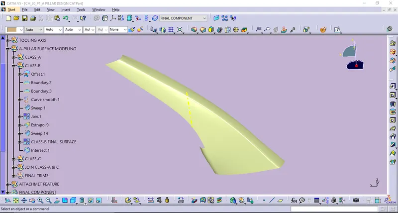
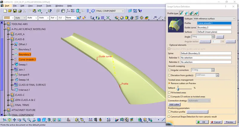
By using of Type-1 Swept surface definition with respect to the apropriate profile and Guide curve.
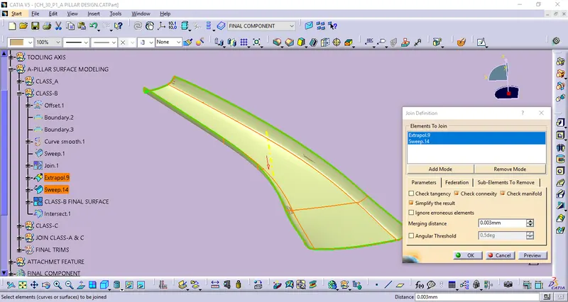
By using Extrapolate & Join Defition final B side surface obtained.
STEP_2: CLASS-C SURFACE CREATION
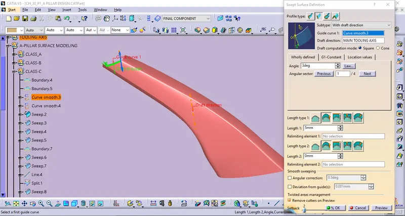
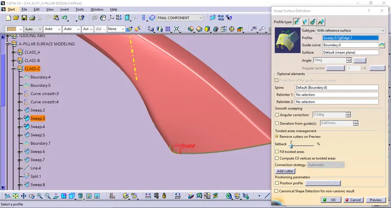
By defining the Class-C surface with respect to the Class-A surface. From the Class -A surface edge boundaries used to performed to create the Class-C surface. And the some of its workings are,
Commands used: Swept surface(type-2) with drfat direction , Swept surface(type-2) with ref surface, Swept surface(type-1) with ref surface along with the profile and guide curve, Boundary, Curve smooth, Extrapolate, & Trim.
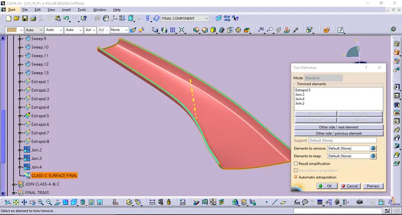
STEP_3: JOIN CLASS-A & C
By using of Join Definition.
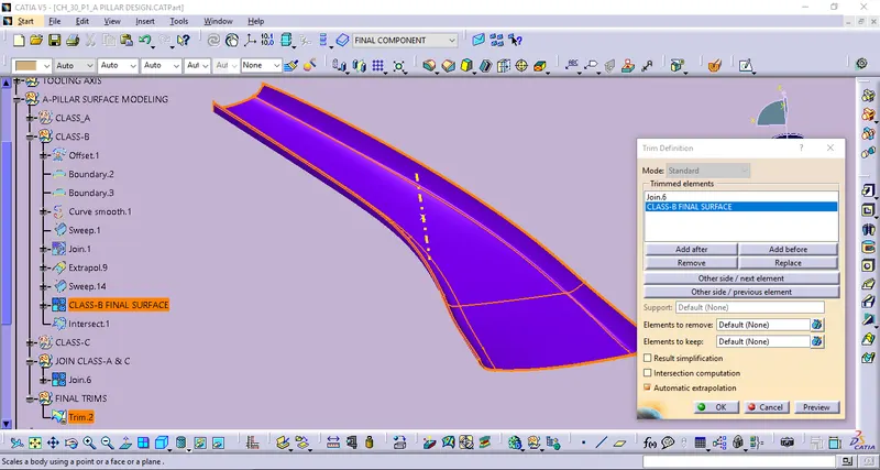
STEP_4: FINAL TRIMS
By using of Trim Definition.
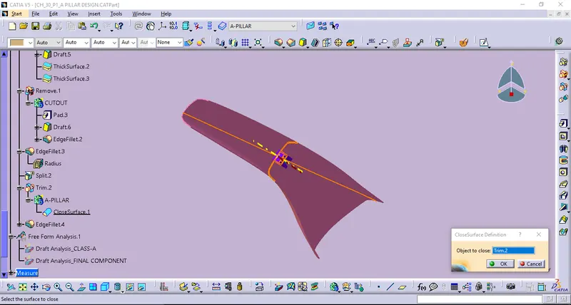
STAGE_4: SOLID PART_CLOSE SURFACE
By using of Close surface Definition.
STAGE_5: ATTACHMENT FEATURE CREATION & ITS DRAFT ANALYSIS
DOG HOUSE CREATION
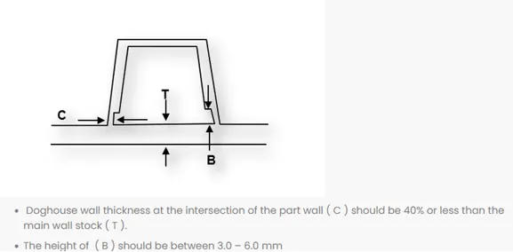
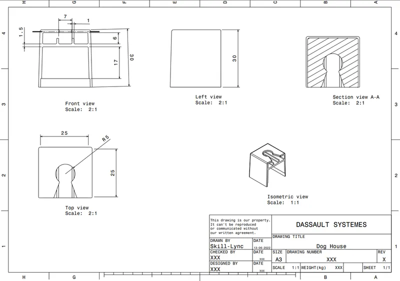
Dog house is an engineering feature used in plastic trim design. Dog houses are used as supporting feature. Sometimes other engineering features like snaps; locators etc. are mounded on them to increase their strength.
Design Considerations are,
- Uniform wall thickness
- Corner Radius
- Draft Angle
INPUT
:
SOLVINGS:
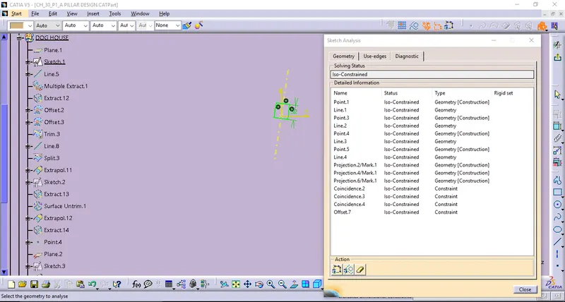
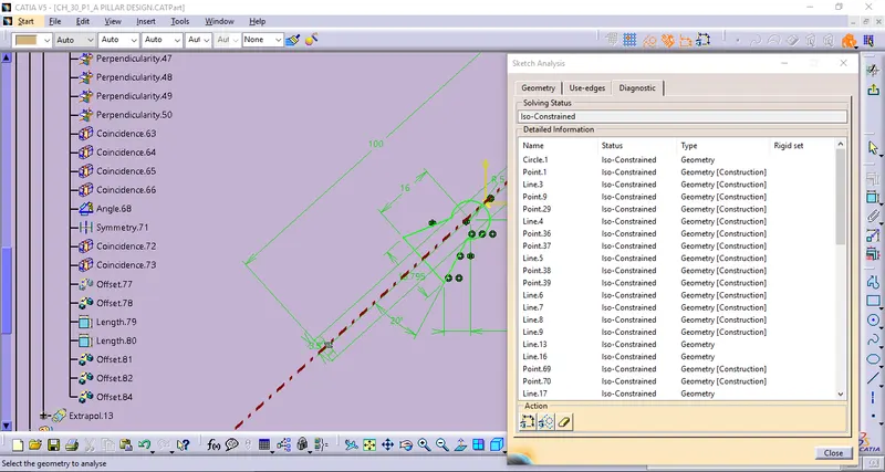
Thus the following as traced out from the given Master section & it also Iso constrained Sketch(Positioned sketch).
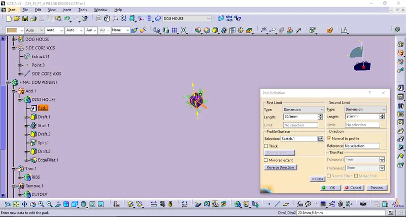
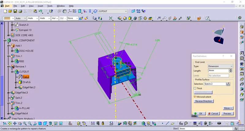
By defining Pad definition.
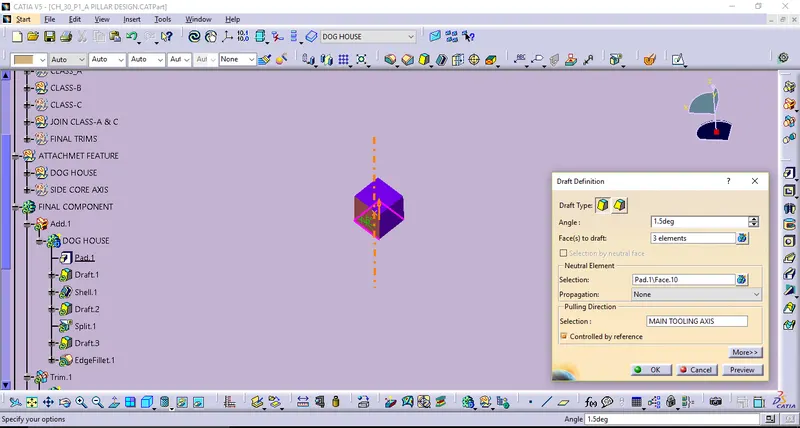
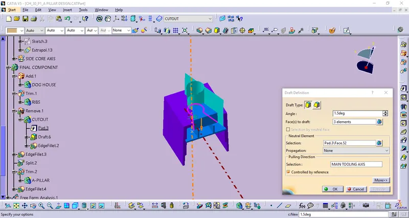
By defining Draft definition along with the main tooling axis with the angle of 1.5 deg.
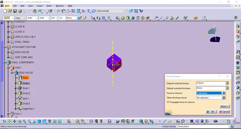
By using of Shell definition thus the thickness will formed here.
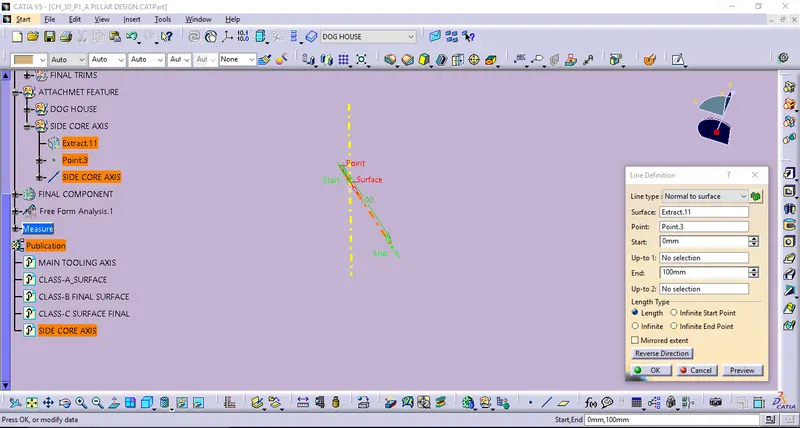
Creating Side core axis line.
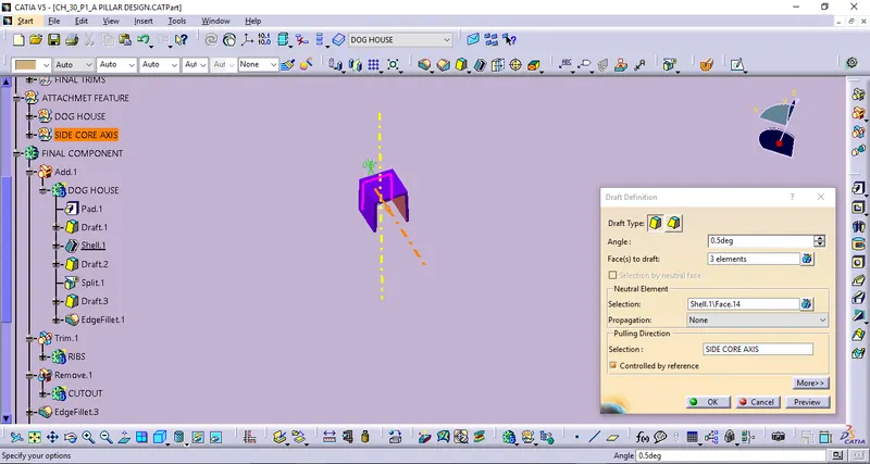
By using the above Side core axis we could define the inside drafting by following like,
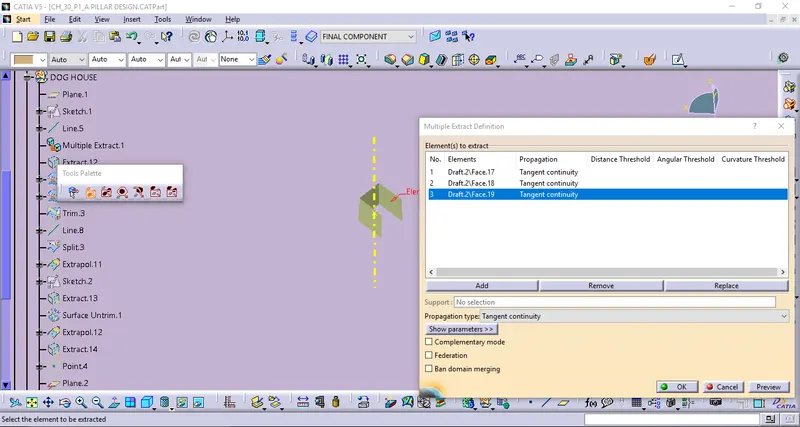
By using of Multiple extract definition.
By using of Extract definition.
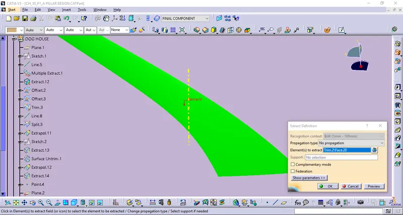
By using of Offset surface definition.
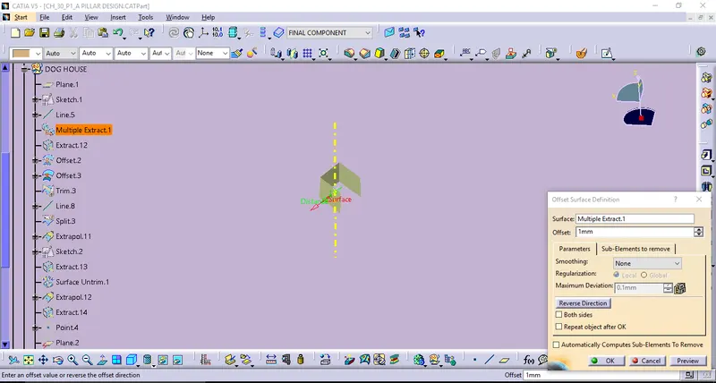
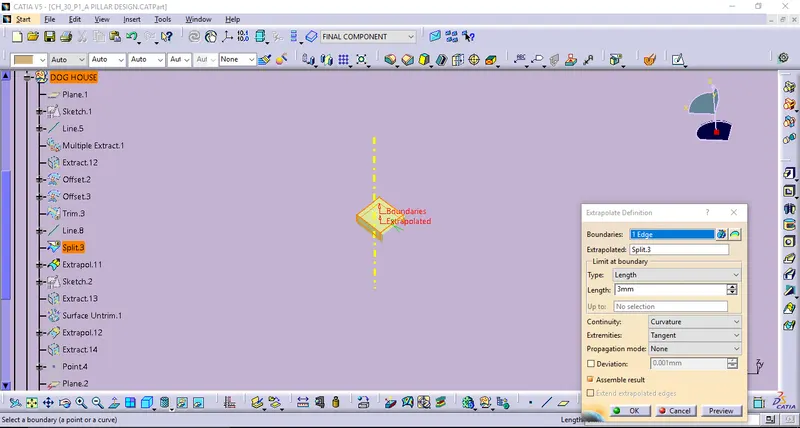
By using of Offset, Split then Extrapolate definition we obtain the Coring surface by using 40% thickness.
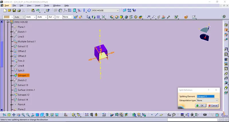
By using Split definition.
By using of Drfat definition.
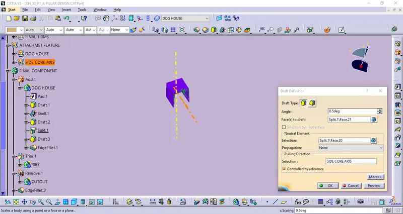
Thus the following as traced out from the given Master section & it also Iso constrained Sketch.
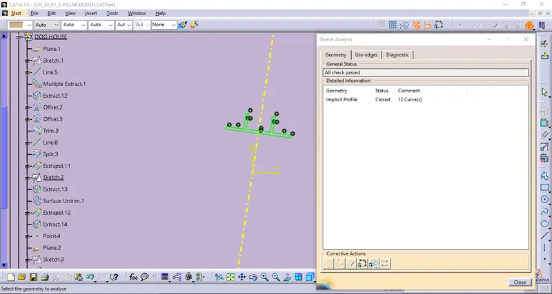
By using Pad definition.
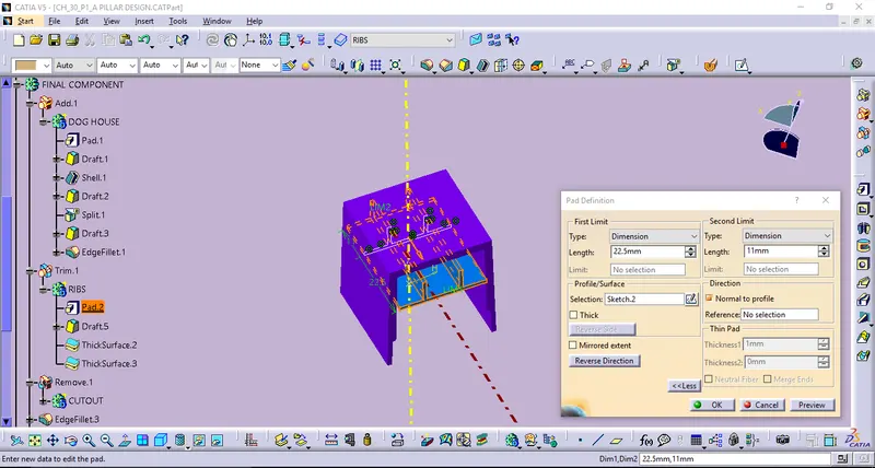
Byusing Draft definition.
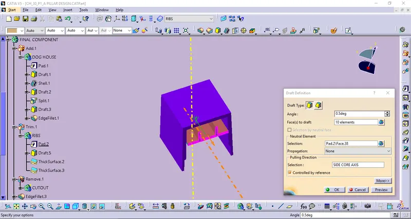
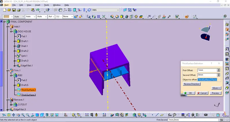
By using thicksurface definition.
Iso-constrained sketch(Positioned sketch).
By using of pad definition.
By using of draft definition.
STAGE_6: OBTAIN FINAL COMPONENT_BOOLEAN OPERATIONS
By using of Add.
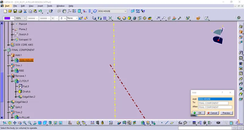
By using of Union Trim.
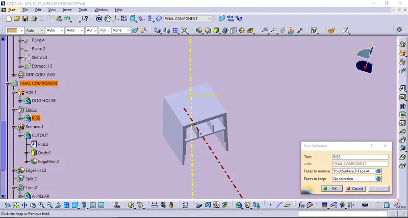
By using of Remove.
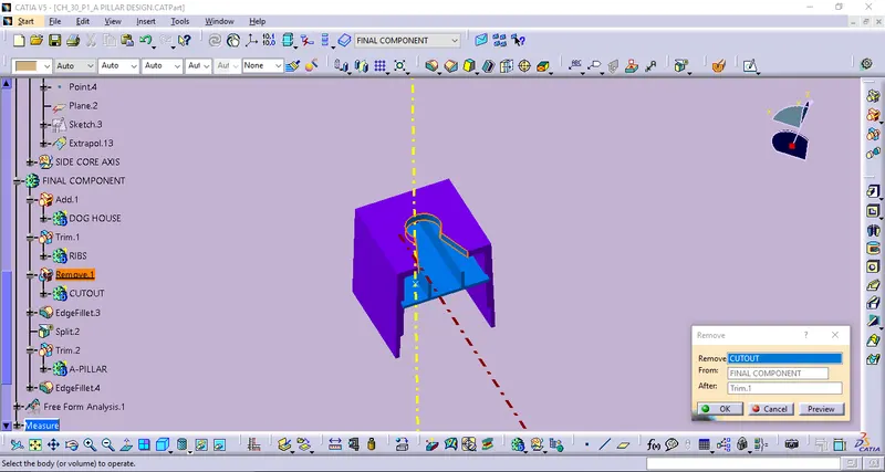
By using of Union Trim.
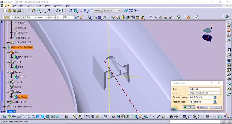
By defining dress-up features over ther By using of Edge fillet definition.
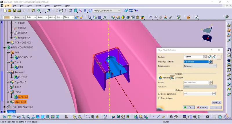
Draft analysis over the Dog house of this component with the angle of 0.48 deg along with the side core axis.
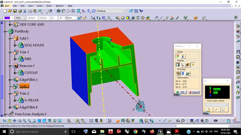
STAGE_7: DRAFT ANALYSIS FOR FINAL COMPONENT
Draft analysis for the final component along wint the main tooling axis wint the draft angle of 1.48 deg.
VIEW ORIENTATIONS:
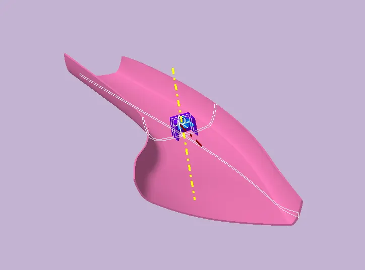
ISO VIEW
SECTION VIEW
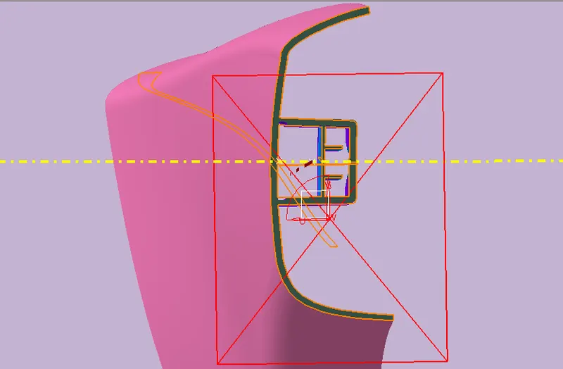
SIDE VIEW
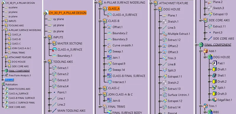
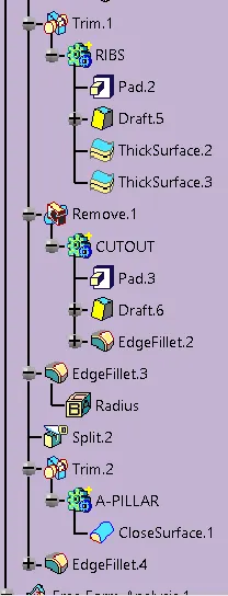
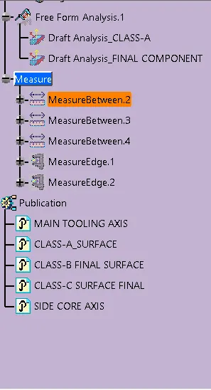
TREE STRUCTURE:
CONCLUSION:
Thus the A-Pillar design with the Master Sections plastic Component successfully created by using CATIA v5.
And the followings also,
Tooling axis for the given Class-A Surface and its Draft analysis to be completed.
B side Attachment Features in the component & its Draft analysis for both the Dog House along with Side Core Axis and the Final component completed.