Week 9 - Project - A pillar Design with Master Section
A Pillar Design with master section
Aim :
To create the A Pillar Design with the master section given as the intersection sketch with the Class A surface and create the tooling axis and perform the Draft analysis for the final solid part.
Objective :
- Create the required Tooling axis by using master section and bisecting methode.
- Design the Class-B and Class-C surfaces and close all three surfaces.
- Design the Dog house and its internal parts as given Drafts and mater section sketch.
- Draft analysis for the final solid part and side core Draft analysis.
Theory :
Tooling Axis :
Class-A surface is first analyzed to create the tooling axis or tooling direction that molds pull apart in injection molding. Tooling direction is important for plastic product design as it decides direction for mold seperation.
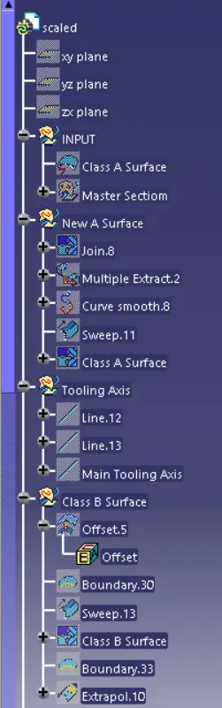
Step followed for creation of tooling axis :
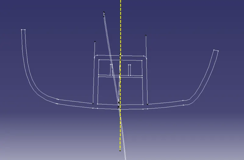
- Extend the sides of dog house of master section by drawing line on the edges .
- create a line bisecting both the edges from the point between both the edges.
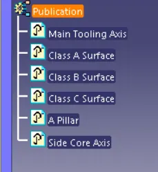
- the line created bisecting both the lines is our main tooling axis as shown below.
Draft analysis :
- The part created has to be changed to material mode in display frame.
- Compass is enabled and align it along with the tooling direction.
- Lock command is then classified and Draft angle is applied.
- Color codes are classified and Draft angle is applied.
- Running point analysis is used to display permissible draft angle.
Draft analysis for Class-A surface :
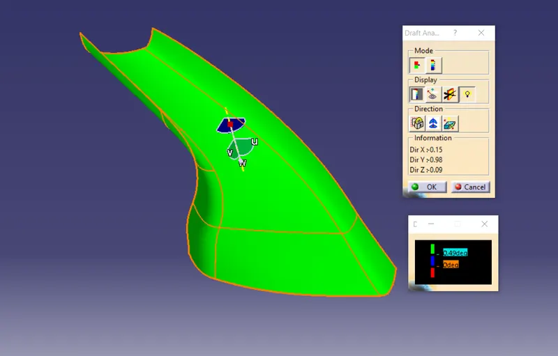
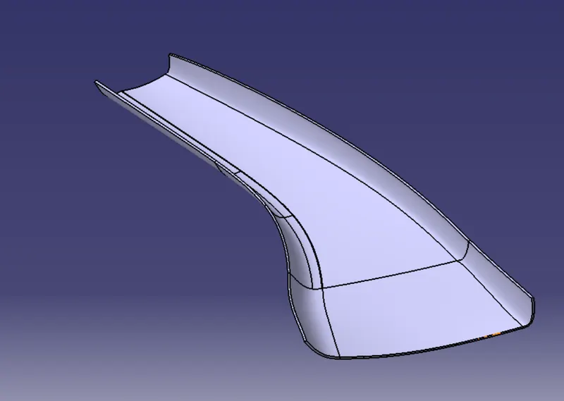
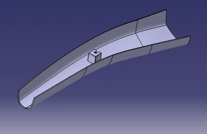
Given Class-A Surface :
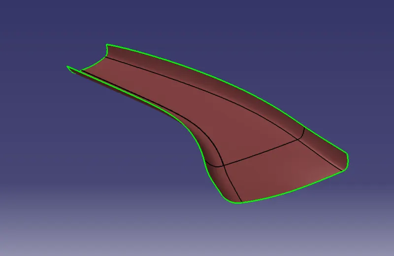
While offseting class A for Class B surface i found some mismatch and a big patch was removed which cannot be formed by any operation so class A must be modified to remove that problem.
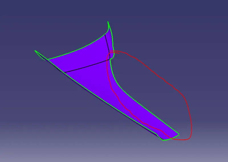
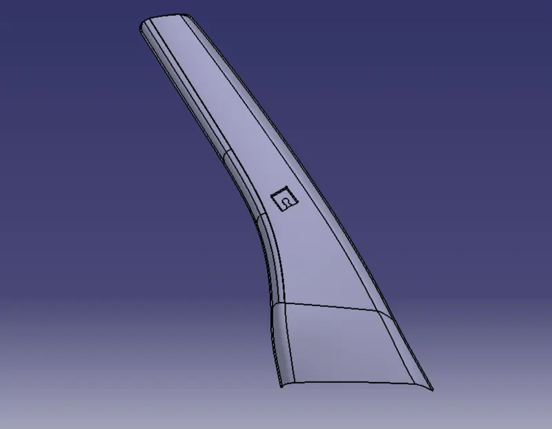
for resolving this issue i modified the class A surface which is shown below.
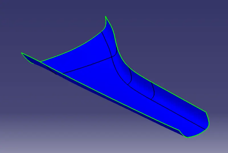
Created Class-B surface :
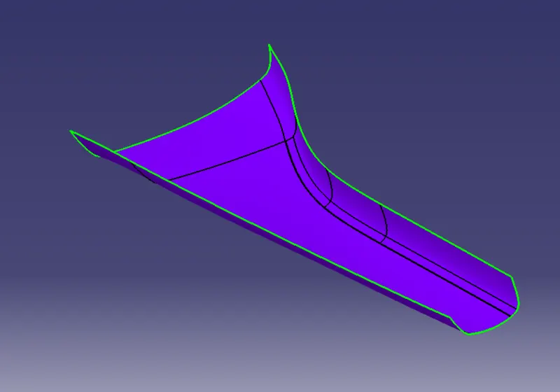
Created Class-C surface :
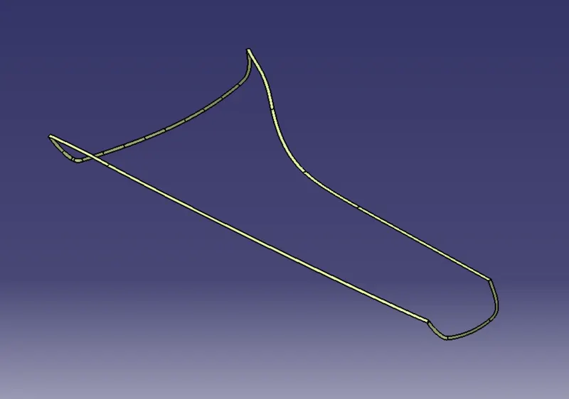
Closed surfaces :
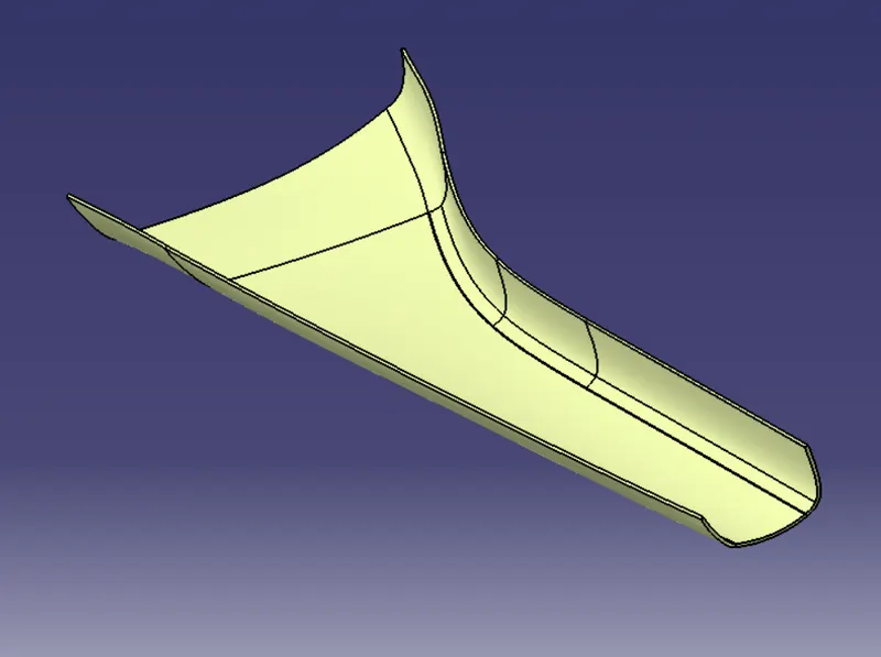
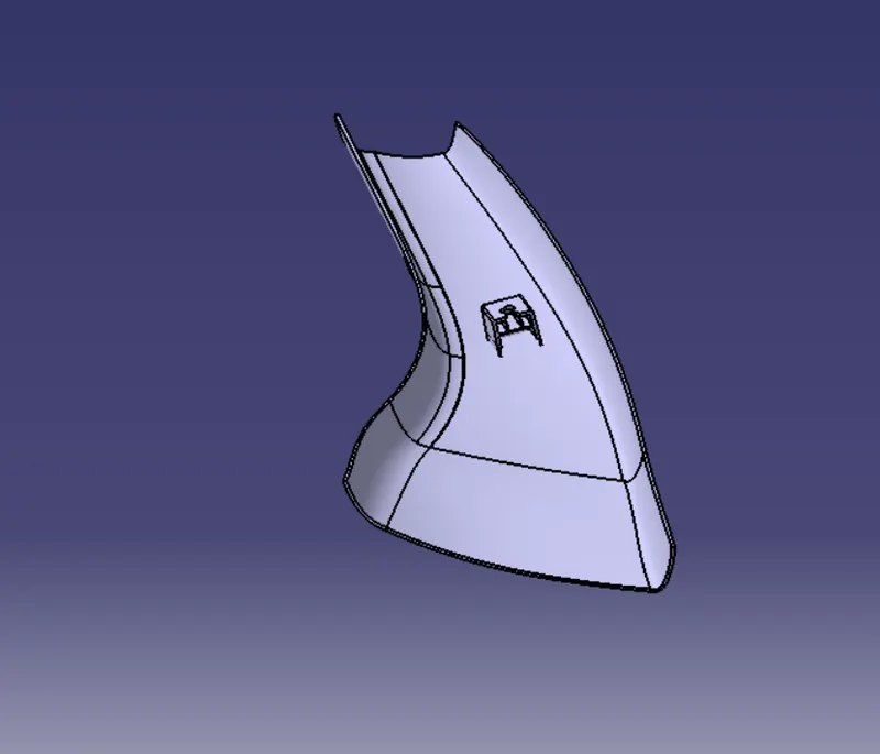
Generated solid A pillar surface
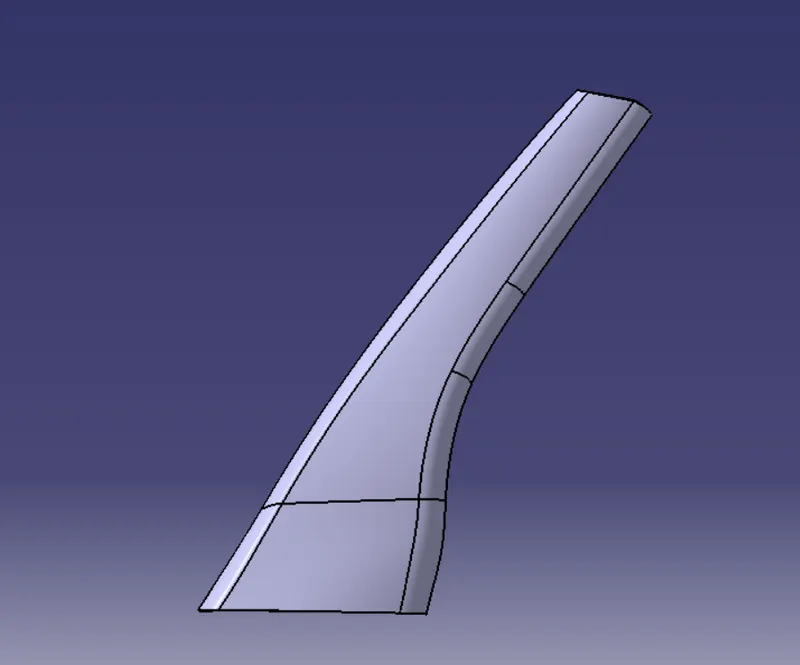
Given Master section
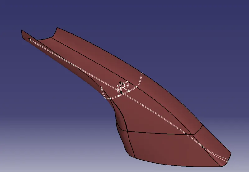
Given 3D view of Dog house :
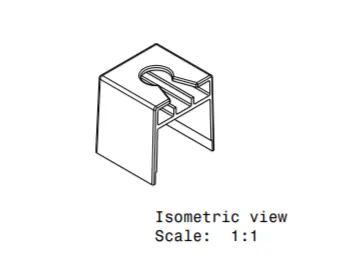
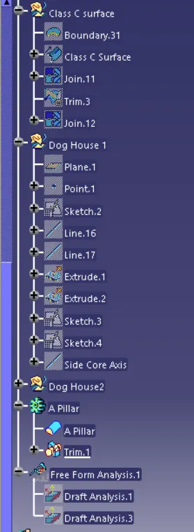
Creation of Dog House :
Sketch for Dog house :
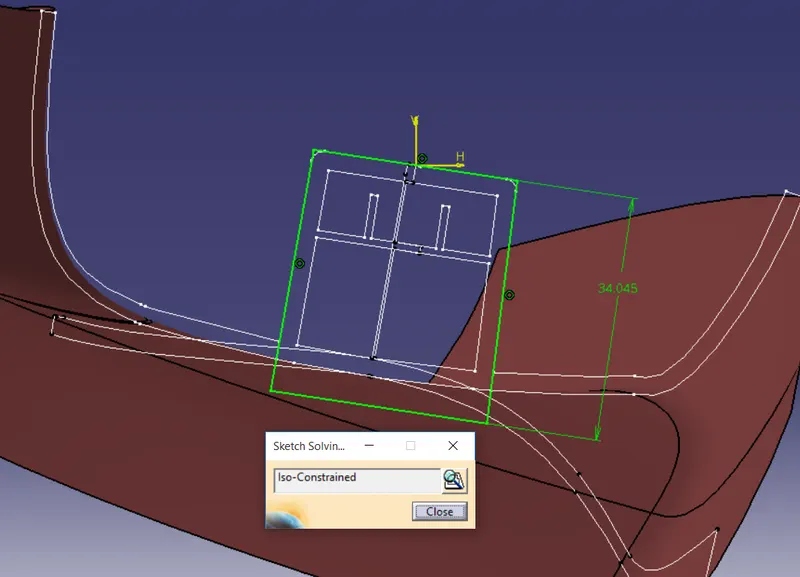
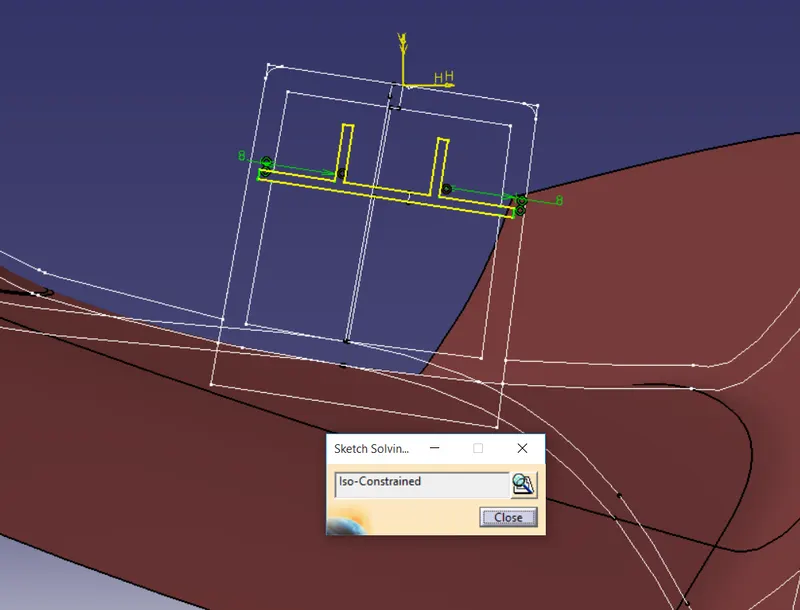
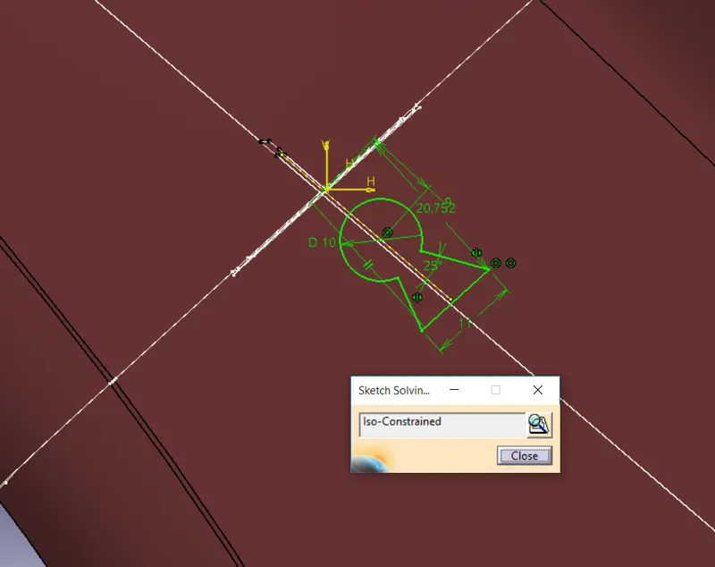
Sketch for Cutting Element :
Final Dog house :
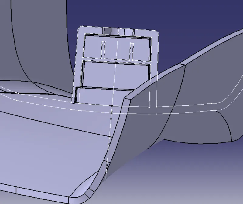
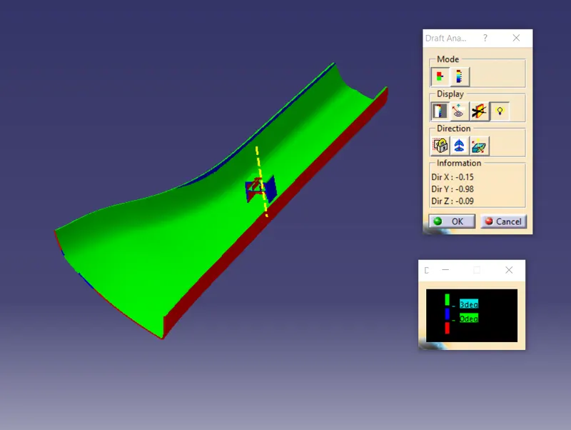
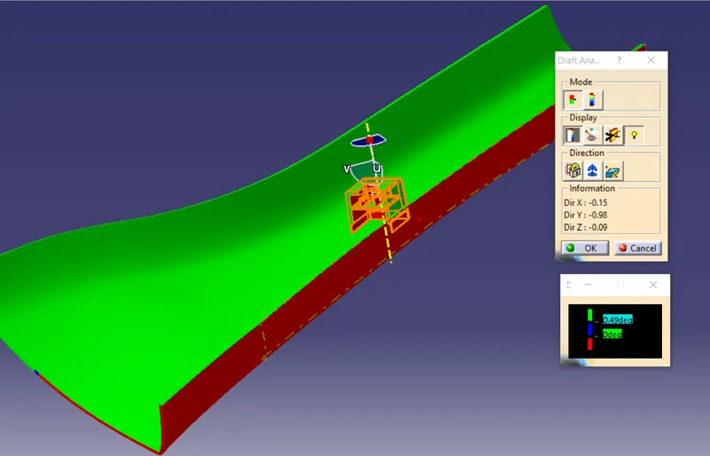
Drafts of 0.5degree are provided inside the dog house in the direction of side core axis so that its for removal of side core.
Draft analysis :
- The part created has to be changed to material mode in display frame.
- Compass is enabled and align it along with the tooling direction.
- Lock command is then classified and Draft angle is applied.
- Color codes are classified and Draft angle is applied.
- Running point analysis is used to display permissible draft angle.
Draft Analysis For final solid part :
For 3 Degree
For 0.49 Degree
Conclusion :
Hence the A Pillar Design with the master section given as the intersection sketch with the Class A surface is done sucessfully and create the tooling axis and perform the Draft analysis for the final solid part is also done successfully. From the Draft analysis for class A surface some areas in minimum of draft angle of 2.66 Degree so we need to correct it Class A surface itself by informing to the Class-A surface creating team.