Week 9 - Project - A pillar Design with Master Section
Aim: Draft analysis of an Automobile A-Pillar created using surface commands with reference to the master section.
Theory: -
Draft angle: A draft angle is a slant that is applied to each side of most features of an injection molded part. The angle, which is positioned to run toward the direction of a mold's pull and parting line, helps with releasing the part from the mold.

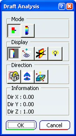
Draft analysis: The Draft Analysis allows the user to easily analyze a part for a proper draft angle. A Draft Angle describes the amount of taper for molded or cast parts perpendicular to the parting line. Find the Draft Analysis in the Tools tab. Draft Analysis is applicable for 3D part models.
Pillars of Cars significance: -
>Car pillars are components that support the structure of an enclosed automobile body.
>Body pillars are critical in providing strength to an automobile body.

Significance of Master Section:-
>Master sections are the guides for design requirements that decide the component packaging after technical (Styling, Concept, or Class-A) surfaces.
Tool Axis Creation: -
In Molding, machine arrangement is given to open the mold along a direction which is known as Tooling Direction.
1.To create a tooling axis, one may use the following methods, i.e
> From a large circular contour
> From a large flat surface.
>Line Bisecting Method.
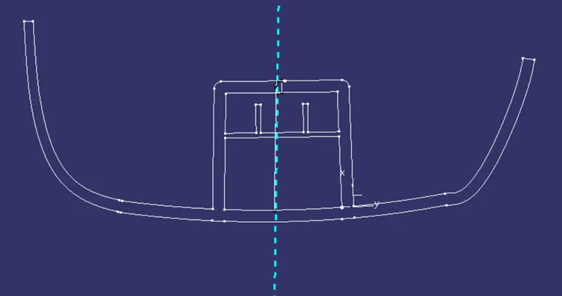
>Taking reference from Master Section
2. In the model below, the tooling axis drawn from taking a reference from the master section.
3. Now we move on to make the B Surface: -
As there are different components in the body, hence it is recommended that one should segregate and split the parts for easy surface generation and also cascade the components in an orderly manner.
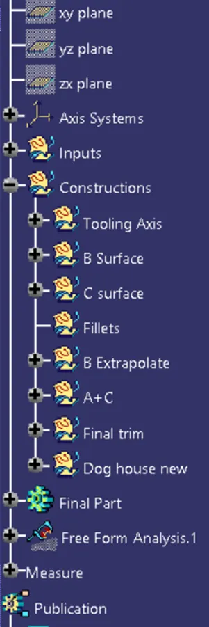
> For Surface Generation we first offset the Class A Surface and then we use the ‘Join’ and ‘Sub-element to remove’ commands to remove any holes and gaps as from offsetting a large surface, some of the fillets may not be generated.
> Now we measure the fillet from the Class A surface and as surface B is inside the Class A surface, hence we will add the thickness value along with the fillet value.
>We can then use commands like multisection solid or sweep for surface creation.
Note: For areas that are too intricate, then we may give the exact value of the fillet or give a nominal value to the fillets for smooth surface generation.
> Now we move to make the C surface, where we first make a boundary at the edge and use the ‘Sweep command’ for surface generation.
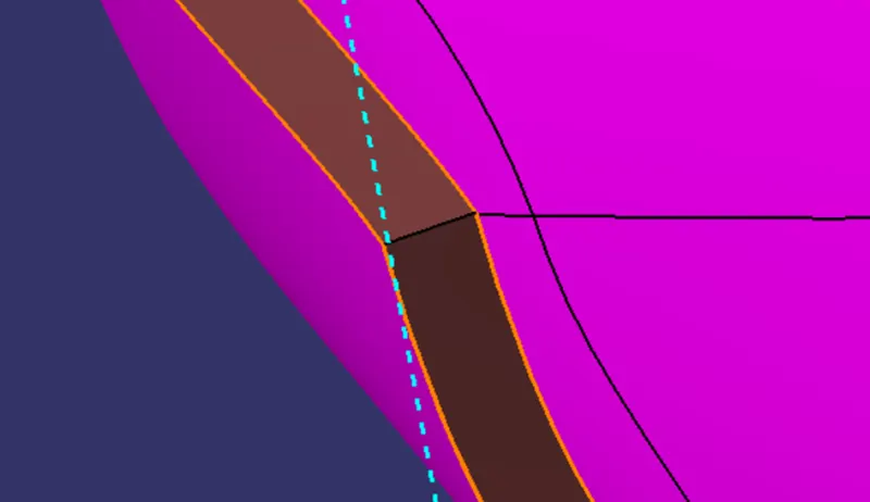
Note: One should always remind that B Surface should not be generated above the Class A surface as the Class A surface holds the aesthetic value and comes in direct contact with the consumer, therefore no changes should be made to the class A surface.
Dog House Creation:-
Master Section provided:-
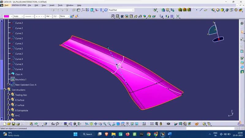
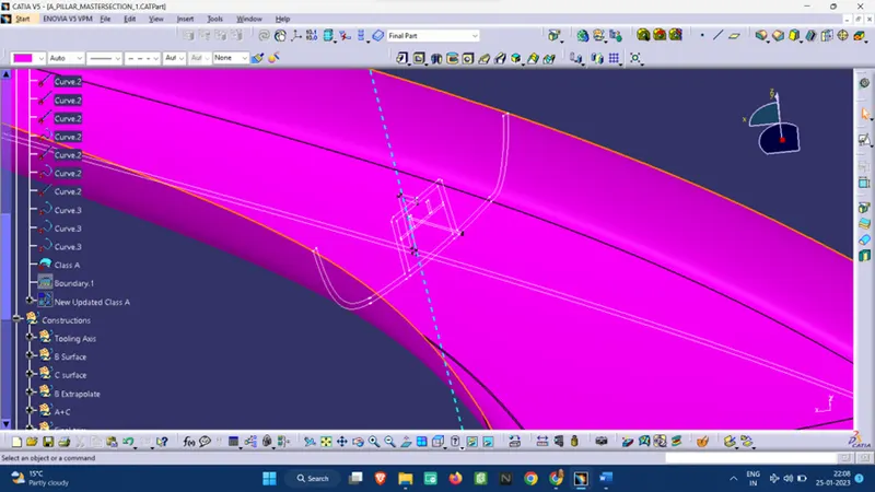
> At first we need to have a sketch of the boundary of the dog house for which we can do the following:-
> Make an Axis system parallel to the master section.
> Taking reference from the master section projections sketching the outlines of the dog house.
>Following this we extend the lines and trim the excess part and then we insert a body
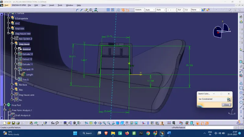
> After creating the side walls with Extrude, we then thicken the surface
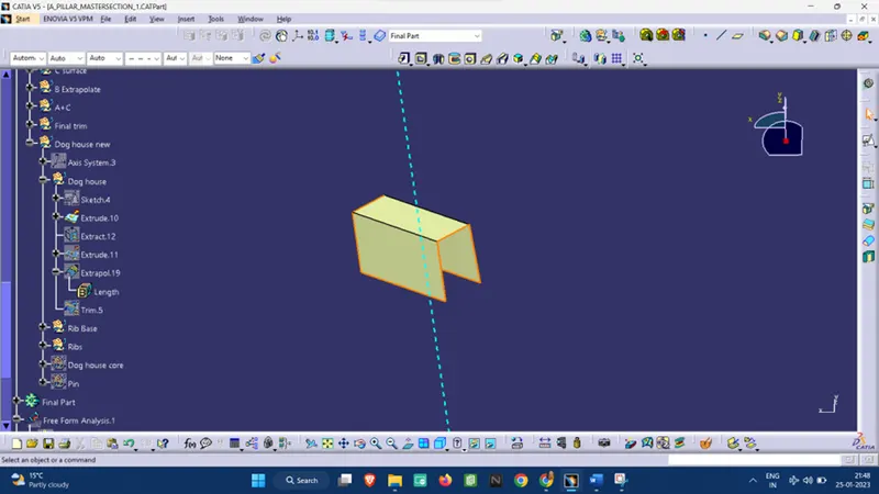
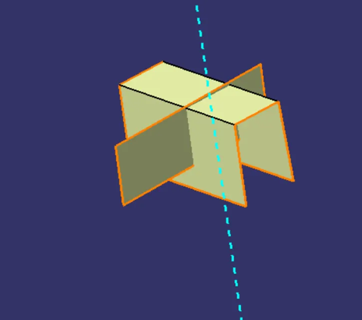
> Now we provide a 0.5 deg draft to the inner surfaces.
> We need to create a side core axis for the internal draft of the dog house.
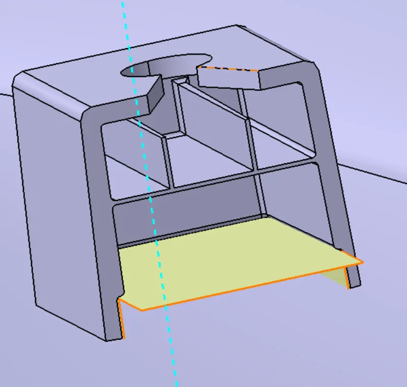
> Then we create the Undercut using an offset command and Split command.
> Now we Union trim the excess surface of the Dog house from the main body.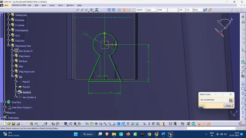
Draft analysis:-
Standard Measurements:
Model Thickness: 2.5 mm
The minimum Draft angle provided: 3 deg angle (Main body)
1.5 deg angle (Dog House outer walls)
0.5 deg angle (Dog house inner surface)
Calculations:-
Wall Thickness of the dog house = 2.5 mm (As per Master section)
Wall Thickness of the undercut = 0.4*2.5=1 mm
Fillet radius on outer dog house body= 1.5 mm (As per Master section)
Fillet radius inside dog house body= 0.5 mm (Nominal value)
Draft Analysis:-
Class A surface Draft analysis:-
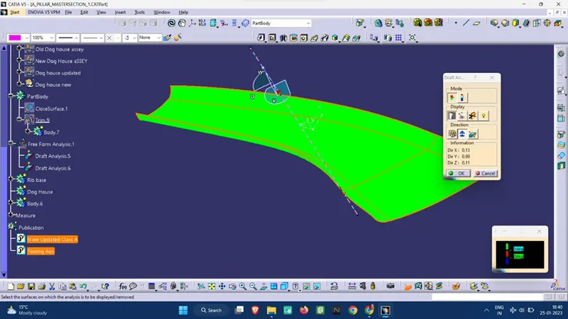
Final Body draft analysis: -
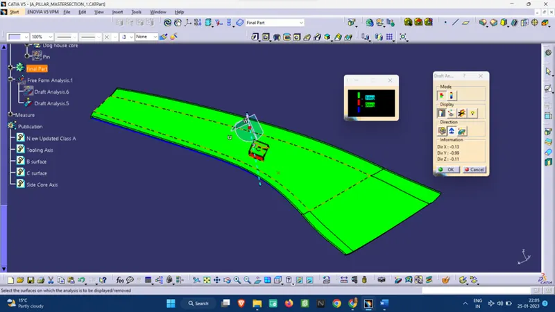
Note: The dog house outer walls are showing red color as they are drafted at an angle of 1.5 deg.
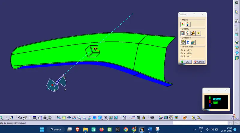
A different view of the draft analysis:-
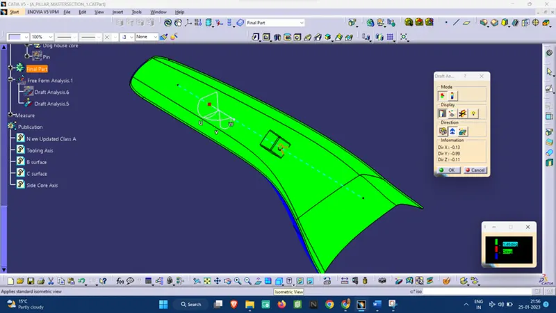
Isometric View: -
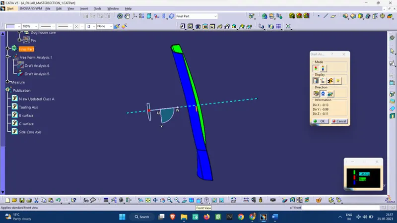
Front view: -
Side View:-
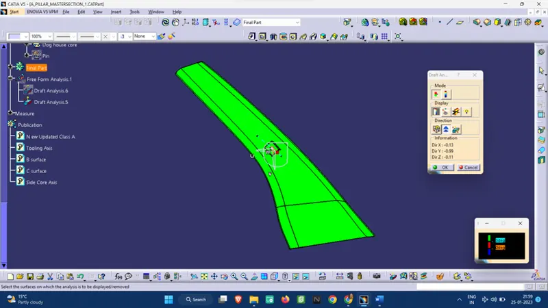
Top View:-
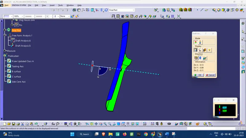
Draft analysis of the Dog house:-
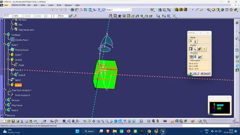
Draft analysis with the Tooling Axis:- (Blue line is the tooling Axis)
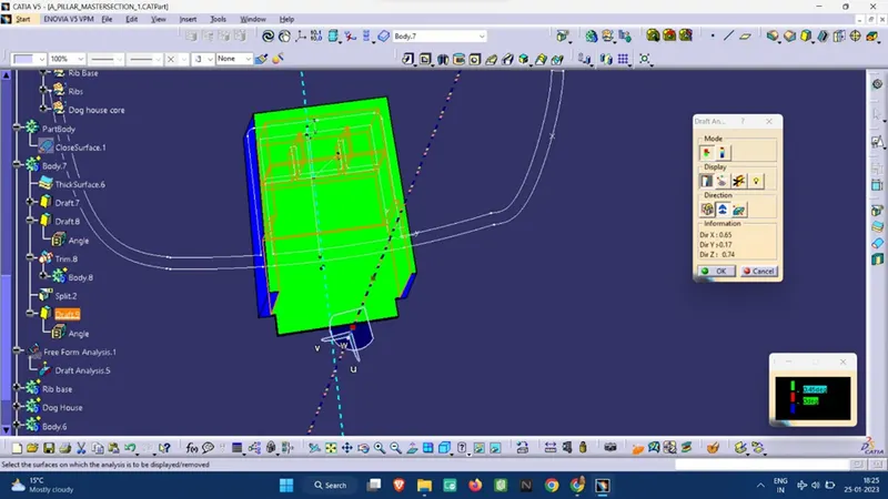
Draft Analysis with the side Core axis:- (pink line is the side core axis)
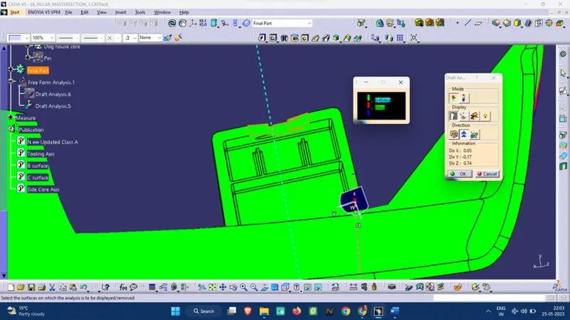
Note:
Green Surface: Denotes that the model satisfies the required draft angle
Blue Surface: Denotes that the model draft angle is below the required draft angle.
Different surfaces:-
Class A surface:
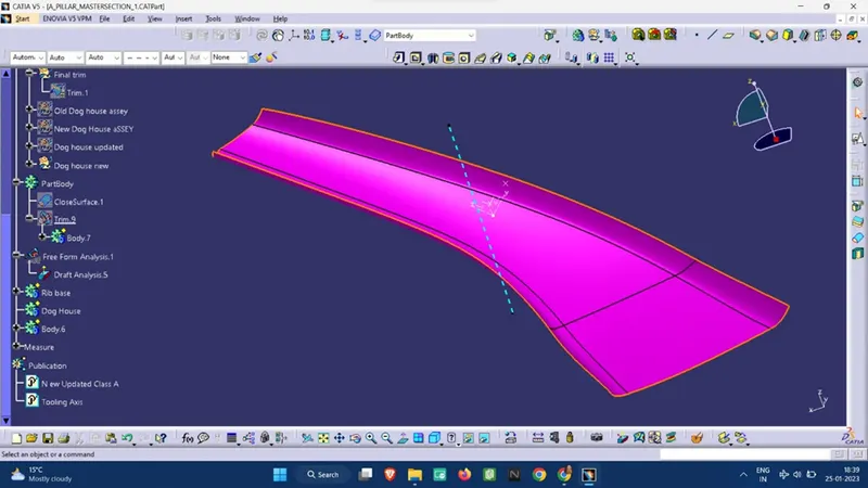
Class B surface:
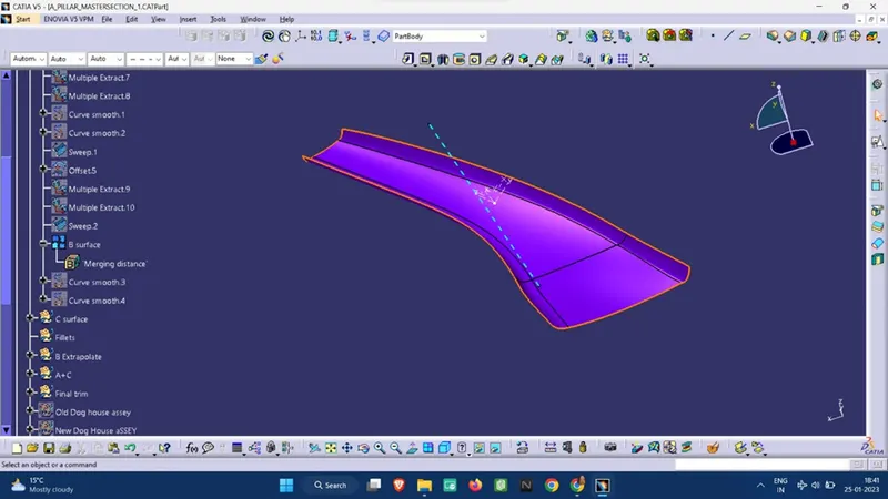
Class C surface:
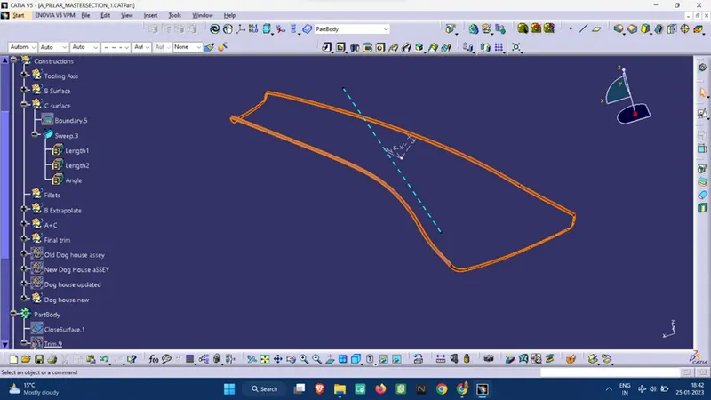
Note: To generate the Class C Surface, we have used “Sweep Command” along with the “Reference to surface” option at 93 degrees (3 Deg as Draft angle), as in this part the C surface is at a right angle with the Draft axis.
Conclusion: Draft analysis is a very essential tool for manufacturing a plastic product using Core and cavity manufacturing techniques, hence draft angle should always be provided appropriately.
Dog House provides two major support:-
> It helps prevent sinkholes.
> It helps to extend the main surface if the screw boss of the joining surface is at a certain distance.