Week 9 - Project - A pillar Design with Master Section
Objective:
- To design and develop B-Pillar from given Class’A’ surface and master section into a functional product design, following the OEM design standards with the injection molding principles.
- The tooling axis for the given Class-A Surface should be created to meet the requirements of the draft angle.
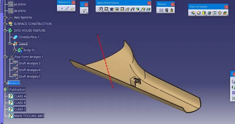
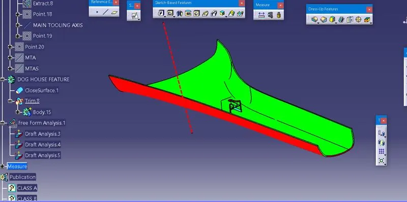
- Perform the feature Draft analysis on B pillar and B side engineering features
- Create the Ribs and Dog House with respect to the given Master section.
Software:
- CATIA V5 (Generative Shape Design)
Introduction:
CATIA V5
CATIA is a multi platform 3D software suite developed by Dassault Systèmes, encompassing CAD, CAM as well as CAE. Dassault is a French engineering giant active in the field of aviation, 3D design, 3D digital mock-ups, and product lifecycle management (PLM) software. It is also possible to generate model dimensions and create reference dimensions in the drawing views. The bi-directionally associative property of CATIA ensures that the modifications made in the model are reflected in the drawing views and vice-versa.
Generative Shape Design
It provides an extensive set of tools for creating and modifying mechanical surfaces used in the design of complex shapes or hybrid parts. Its feature-based approach offers a productive and intuitive design environment to capture and reuse design methodologies and specifications. Help to design advanced shapes that are based on a combination of wireframe and extensive multiple surfaces. It includes high-level features with full specification capture and reuse.
B Pillar
B Pillar is the central pillar of the car. It is the most complex component or structure of the vehicle body. This is because the front door attaches to the B pillar and the rear door hinges to the B pillar. The B Pillar is welded to the top panel of the car and the floor panel of the car. Hence B-Pillar provides structural support to the roof.
Methodology:
- Check for any defects or irregularities in the class-A surface.
- Make a tooling axis.
- Run the draft analysis beforehand in case if there are any faces that do not have drafts, those can be corrected by the class-A designer.
- Understand the master section.
- Make the flange on both sides to make the aesthetic model complete.
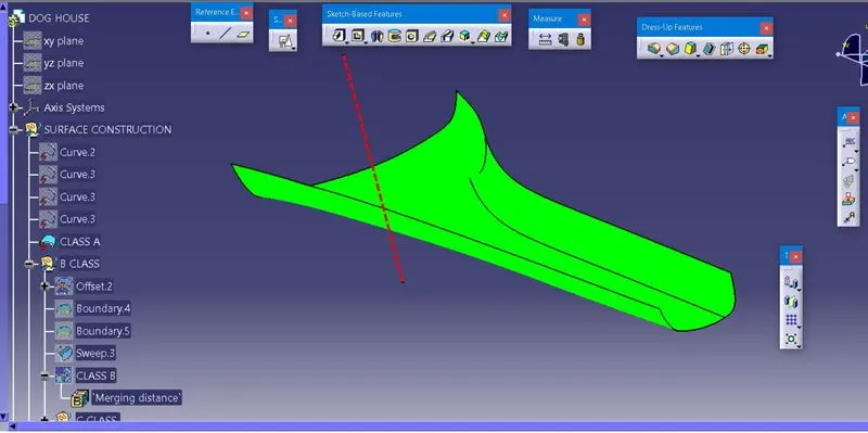
- Make class-B and class-C surfaces.
- Make a close model by trimming surface A, B, and C together.
- Convert into solid the model.
- Make a B side engineering features.
- Perform draft analysis on the final model and make a report.
Procedure with Detail
Procedure for find Tooling Axis
- A Reference Point is created along the Surface zero and a new Axis system is created.
- The X-direction and Y direction along the Class A were used to create the Tooling direction.
- Finally, the Tooling axis is created by bisecting the two lines and it is published. Class A Surface as input using surface operation commands Class B is developed.
- The tooling Axis determines the direction of Class C boundary swept with draft direction.
- When viewing from tooling direction normal all the parts that are drafted should be visible so it gives a rough idea to determine product manufacturing in Injection molding.