Week 9 - Project - A pillar Design with Master Section
Aim :- The Objective Of this Project is to Design the A-pillar by Help of the given Master Section.
Theory :-
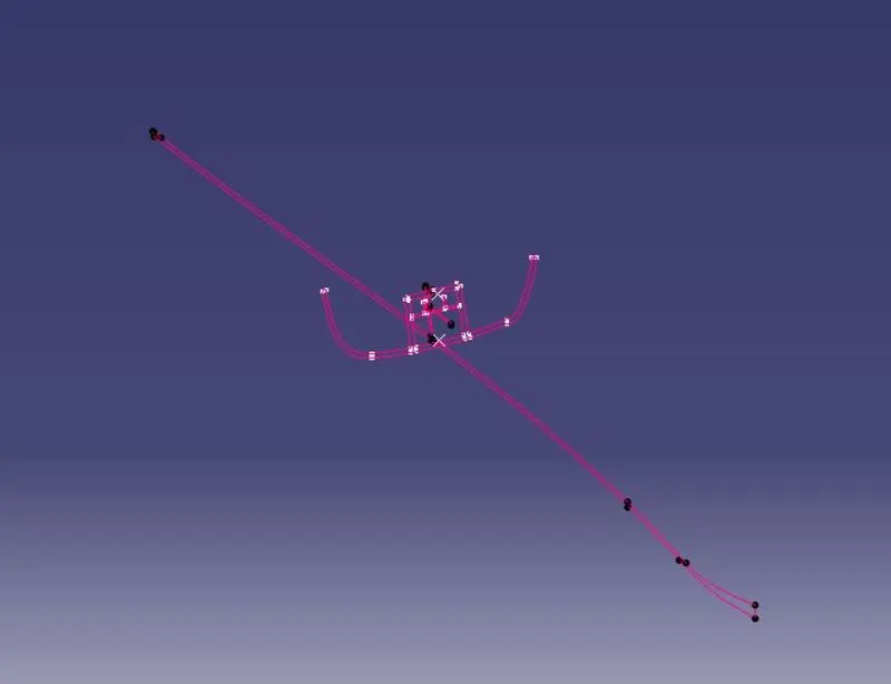
Master Section :-
- Master sections are the guides for design requirements that decide the component packaging after technical (Styling, Concept, or Class-A) surfaces. Creating this master section we should need 5 to 6 years of experience.
- This helps you to decide the feasibility, clearance, packaging, and fixation strategy before working it on a 3D. We have a master section.
A-Pillar :-
-
The structure of an automobile body consists of various support structures like the roof, pillars, and floor.
-
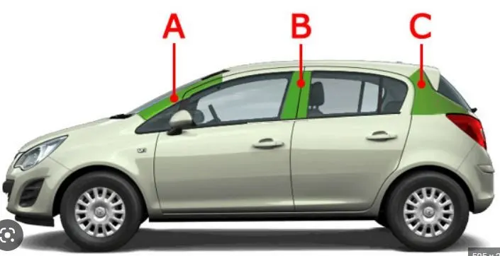
The car pillar in the vehicle stands in the near-vertical position, which supports the vehicle’s roof. The pillars found most commonly are the A, B, C and D pillars.
-
The A pillars are the first set of upright sections on a car body that links the lower body to the roof of the car.
-
It acts as a major support structure during impacts and it is also a median to support the windshield of the vehicle. Apart from structural advantages the A pillar has a large effect on the overall aerodynamics of the vehicle.
Objective :-
- Check the surface continuty of Class-A
- Create tooling Axis
- Draft Analysis Of the Class-A
- Class B Surface Creation
- Class-C Surface Creation
- Make Sure for the Close Surface in Part Design Workbench
- Create the Engineering Feature (Dog House).
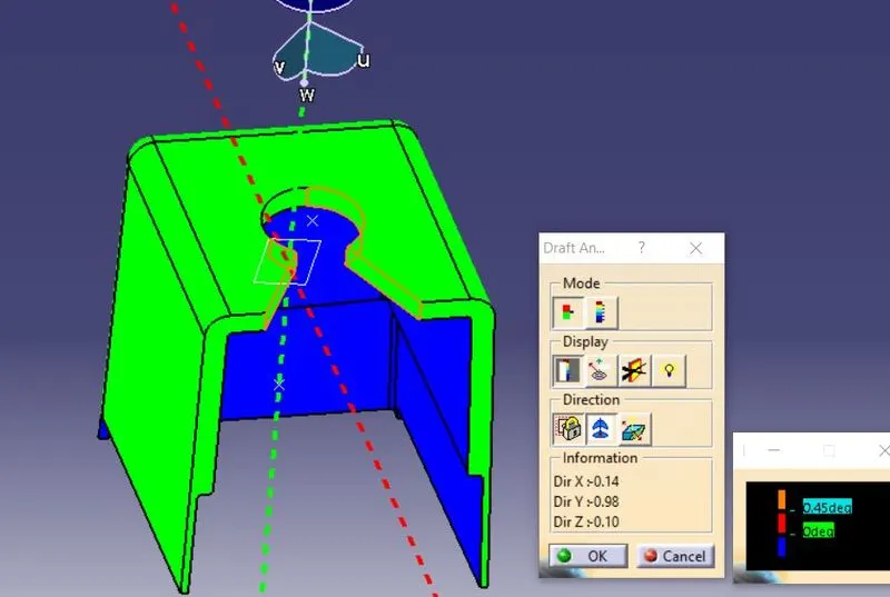
- Make Draft Analysis Of the Dog House And the A -pillar.
Class-A Surface Continuty Check :-
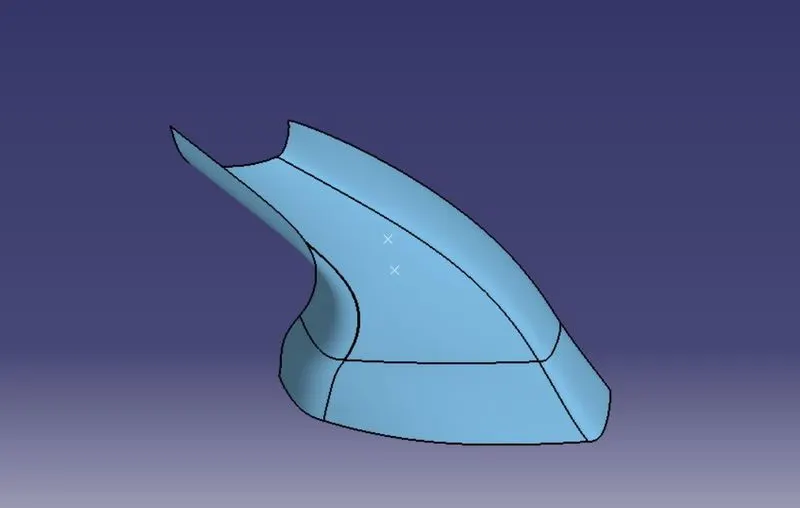
- The Class-A Surface would be provided to us by the styling team of the OEM.
- Class-A surface means visible Styling surface. It gives the aesthetic of the component which is created by the styling team and gives to the part design engineer to create the part with all engineering aspects.
-
The first step is to check the continuity of the class A surface. This is to ensure that there is no gap between surfaces.
-
If we find any gap then we should fix that first.
-
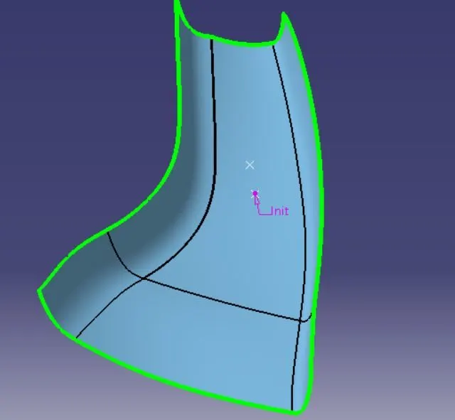
We can analysis the class A surface through visual inspection.
-
To make sure that the given surface has no gap in between them. We can check it through the help of Join or boundary commands.
Creation of the Tooling Axis :-
- The next step is to create the tooling axis for the part which will determine the direction in which the core and cavity of the mould will move.
- Designer must ensure that all holes and slots are covered in the main tooling and thus side core must be avoided whenever possible
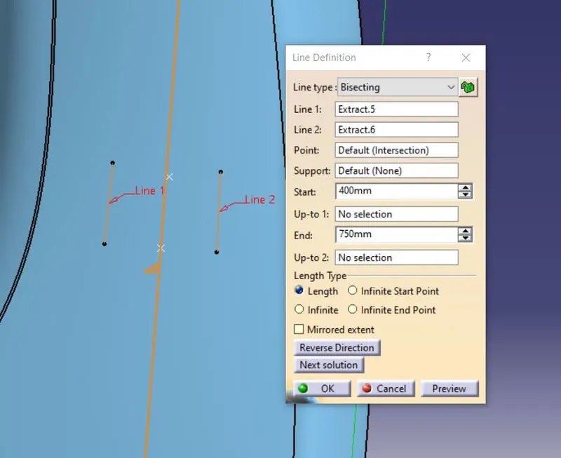
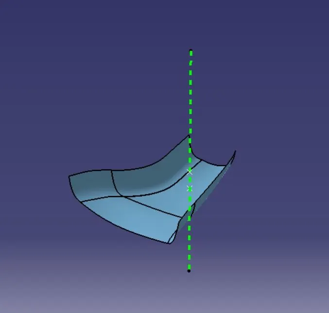
- After analysing visually for the best possible tooling axis, an reference tooling axis is created on the centre of one of the surfaces of the A pillar trim.
- The main tooling axis is created by using the bisecting method and by taking references from the master section
Create Class-B Surface :-
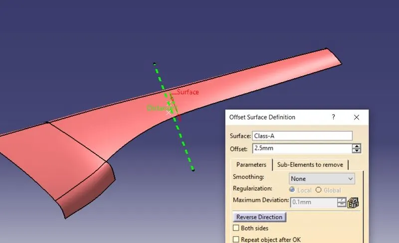
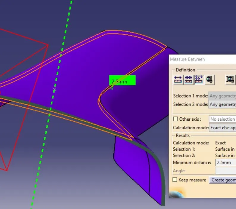
- After all the validation has been done, the class B surface is created by offsetting the class-A surface to a distance of 2.5 mm
- After offsetting a large opening in the surfaces is found which is closed with the help of sweep and multi section commands
- The class B surface is then extrapolated in parts to trim it along with the class C surface.
Creation Of the Class-C Surface :-
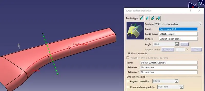
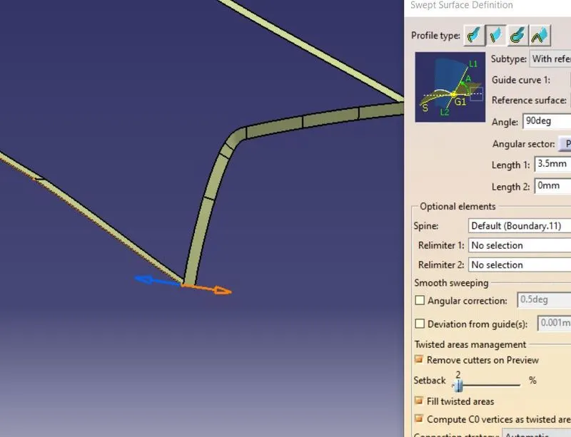
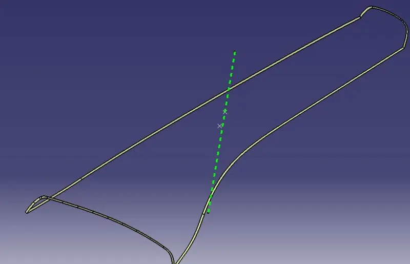
- The class C surface which connects the class A and class B surface is created by sweeping the boundary of the class A and using the class A as a reference.
- The sweep is divided into several parts in order to avoid complexity
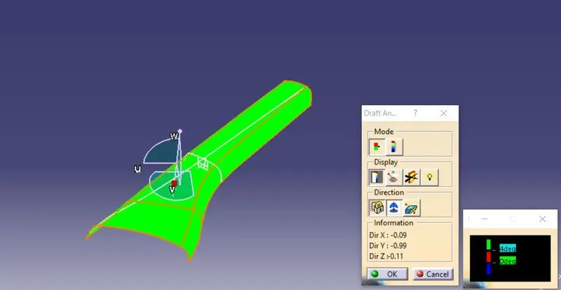
- Surfaces which are parallel to the tooling direction are swept with the tooling axis as reference and with a draft angle of 3degrees
Solid Surface Creation :-
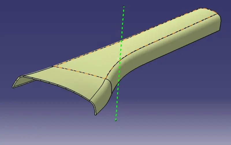
- The final trim is created by joining the Class A and C surface and finally trimming it with the Class B surface.
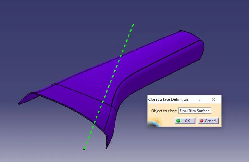
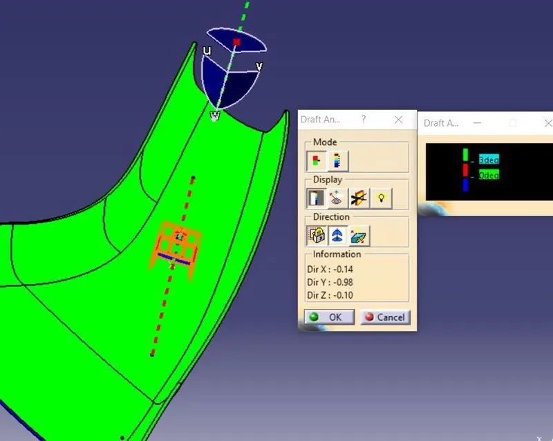
- The combination of class A, B and C surface is then converted into a solid with the aid of close surface command in the part Design workbench.
Creation of the Dog House :-
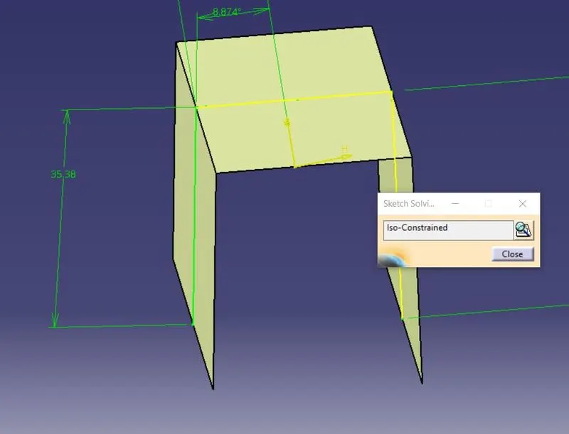
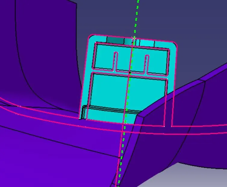
- Doghouses are created by following the design rules. For this, the sketch is created from the master section provided. It is then made into a closed body and is made into a part model.
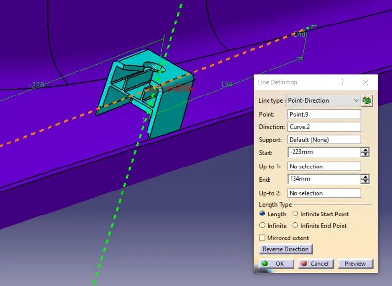
- We need a side core axis, create a line which is normal to the plane formed along the master section. The dog house inner walls and all the ribs will be cleared using the side core axis
- Shell operation is performed to get a hollow structure and then coring is done in order to avoid sink marks on the class A surface.
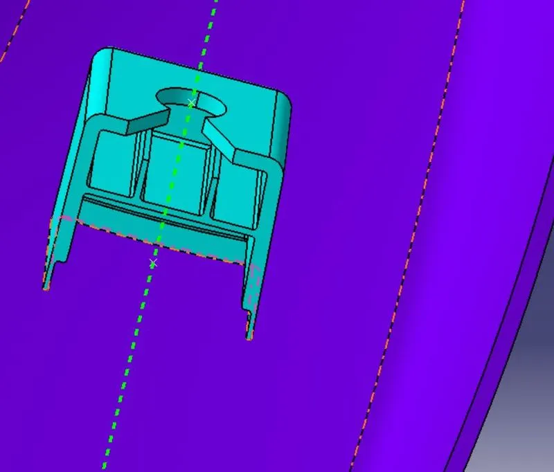
- Drafts are given for the surfaces as per design rules and proper fillets are also provided. As per the given master section, ribs and supporting features are also added to the doghouse.
- Then, the doghouse is added to the main body. All the sketches used are iso-constraint.
Draft Analysis :-
- For molded or cast parts, the draft angle is the amount of taper perpendicular to the parting line. It is measurable in degrees. Because plastic shrinks and sticks on molding surfaces as it cools, we draft the walls of the plastic part so that it ejects or breaks free from the molding surfaces more easily and without dragging.
- To reduce the risk of damage to the parts and ensure ejection, a functional injection molding part must have drafts on both the cavity and core sides.
Nominal values for Draft angles:-
- 3 Degrees is a nominal draft angle.
- 5 Degrees can also be manufactured. Increasing the manufacturing cost.
- 7 Degrees is considered for Textured surface parts.
Importance of Draft in injection molding:-
- Reduces the possibility of part damage due to friction during the release.
- Reduces mold wear and tear.
- Ensures a uniform, smooth, unscratched finish.
- Ensures the integrity and uniformity of other surface finishes and textures.
- Reduces overall cooling time by reducing or eliminating the need for unusual ejection setups.
Steps followed for Draft Analysis :-
- The created part must be changed to the material mode in the display frame.
- Compass is enabled and placed in the direction of the Tooling Axis.
- Then hit on lock command to fix the compass along the tooling axis.
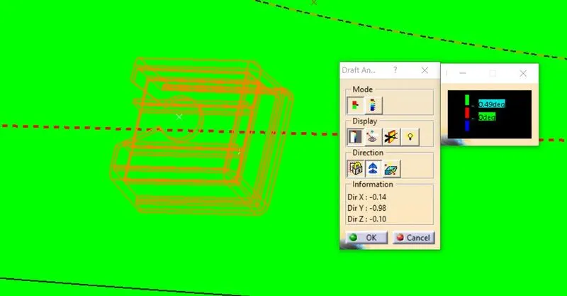
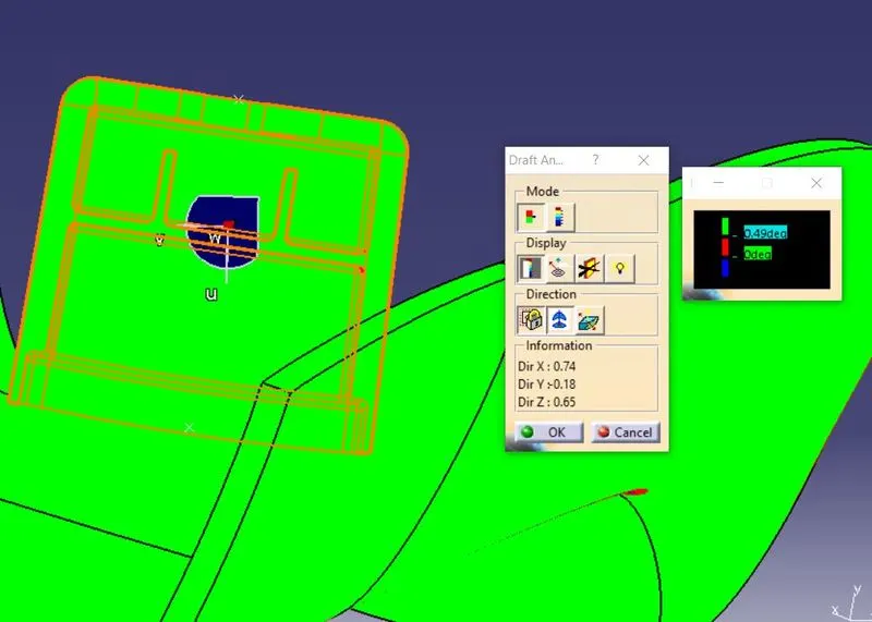
- Colour codes are classified and Draft angle is applied.
- Running point analysis is used to display permissible draft angle.
Class-A Surface Draft Analysis :-
Closed Surfae Draft Analysis :-
Dog House Draft Analysis :-
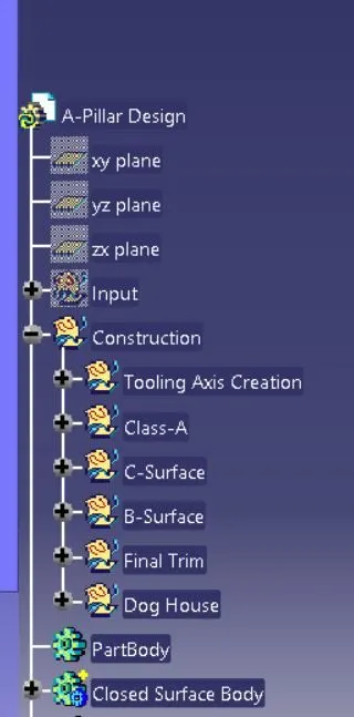
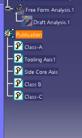
Tree Structure of the A-pillar Design :-
Conclusion :-
The A-pillar Designed Successfully as per the Design rule and the Dog House is also created as per the given Master section .