Week 9 - Project - A pillar Design with Master Section
Aim: To create A-pillar design with Mastersection and using through the given Class A surface and create the engineering feature as Dog House
Objective:
- To create a tooling axis
- To create a Side core axis for the Doghouse
- To design the A pillar plastic component by creating Class B surface and Class C surface using the given Class A surface
- Consider the thickness of the component to be 2.5mm
- To perform draft analysis for given Class A surface and the final closed body.
Class A Surface:
- Class A surfaces are the visible surfaces for the asthetic look and textures.
- The Class A surface is taken from the given resource as show in figure
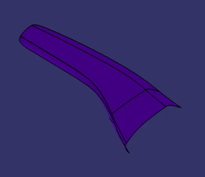
Figure: Class A Surface
- Check the connectivity of the Class A surface using the Join command
- Further to ensure no internal gap are present in the Class A surface check visually or using the Boundary Command, check its boundary.
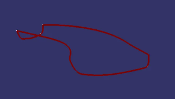
Figure: Class A surface Boundary
Class B Surface :
- Surface with tangent continuity is called as Class-B Surface
- Class B surfaces contains all the engineering features such as Rib, boss, Heatstakes, locator, Doghouse etc.,
- The Class A surface is offset to the 2.5mm to create the B surface
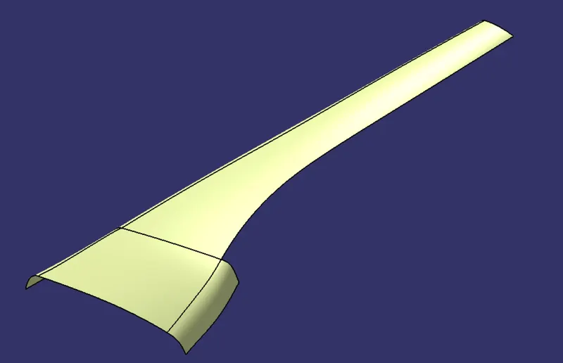
Figure: Offset Class A surface
- To remove some patches in the offset surface, we using sweep command with reference to the surface and the boundary of the edges to get a perfect Class B surface.
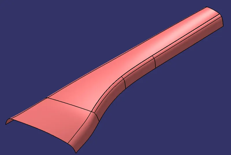
Figure: Class B surface
- Apply boundary command on the whole Class B surface to check any internal gaps if any and resolve them
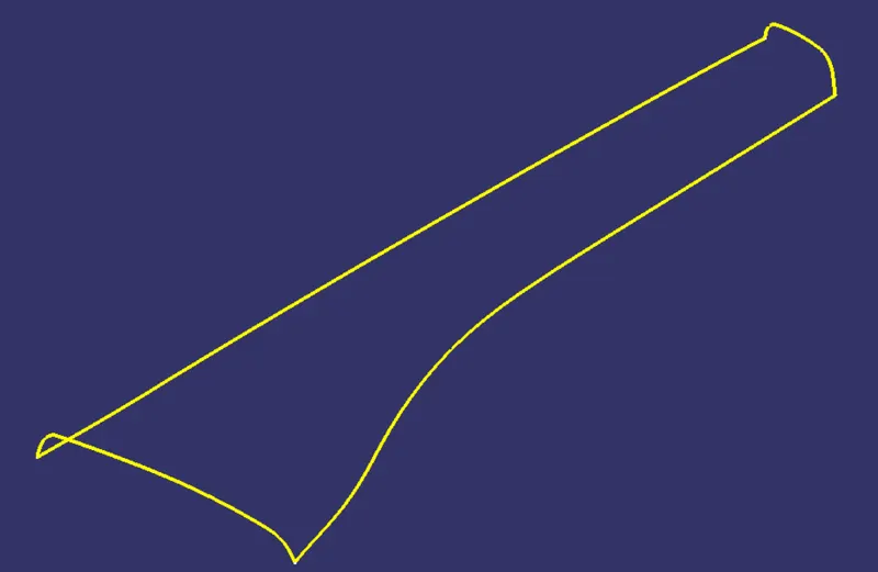
Figure: Class B surface boundary
Tooling Axis:
- Tooling axis is the main consideration for the plastic part and mold parts because it defines movement of the mold parts because if defines the movement of the mold part and possibility of the plastic part to come out from the modl part ( Core and cavity)
- Tooling axis of the A-pillar is created by using the mastersection.
- Firstly, the side part of the Doghouse mastersection are extracted using the Extract command.
- From these extracted lines a bisecting line is created.
- Next, again the front and back lines of the Doghouse mastersection are extracted and a bisecting line is created from these lines passing through the same point as of the first bisecting line.
- Lastly, another bisecting line is created from both the biecting line and this new line is named as "Tooling Axis" .
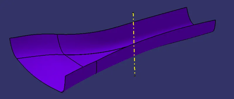
Figure: Tooling Axis on Class A surface
Draft Analysis on Class A Surface:
- The Draft analysis is the command which enables you to detect if the part you drafted will be easily removed. This type of ananlysis will be performed based on the colour ranges indentifying zones of the analysed elements where the deviation from the draft direction at any point, corresponds to the specified value.
- Draft analysis is done after determining the tooling axis, draft analysis is used to check whether the minimum draft is maintained or not.
- Change the view mode of the component to be in customized parameter mode and then select the shading mode as materials.
- Then Using the "Draft analysis" command, click on the compass to define the current drafting direction and lock the compass on the tooling axis and perform the draft analysis by clicking on the Class A surface.
- Click on the analyses under the running point to check the draft analysis on the individual faces. It shows how much draft on specific points when we move the cursor point.
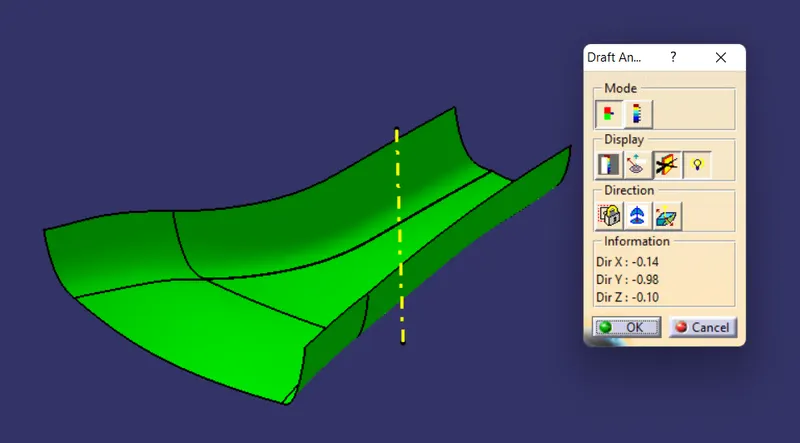
Figure: Draft Analysis on Class A surface
Class C Surface:
- Class C surface joins the Class A and Class B surfaces.
- Using, Sweep command with reference to the surface create the boundary as the guide curve and A surface as the Reference surface.
- Use trim and extrapolate command and finally join all the sweep surfaces.
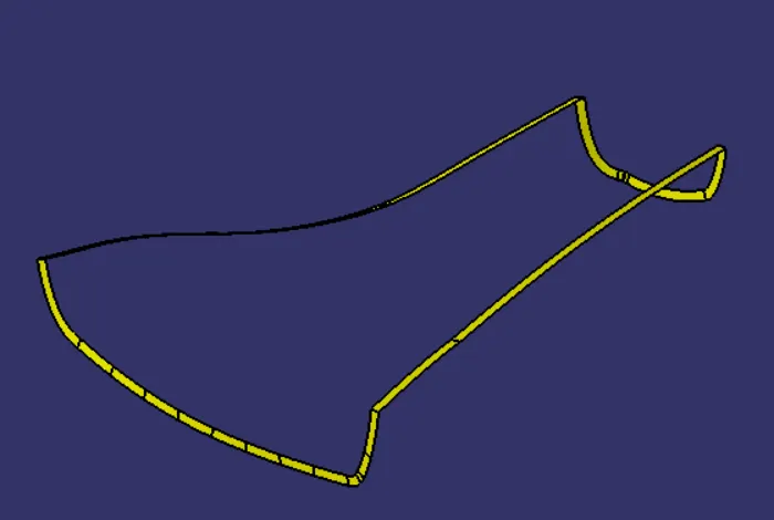
Figure: Class C surface
- Finally join the Class A and Class C surface together
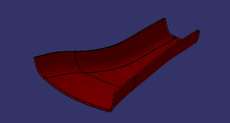
Figure: Class A+C Surface
Final Closed Surface:
- Further, join the Class A+C surface with the Class B surface to create final Closed body
- Some error may arise while applying the trim operation as some surfaces may not intersect each other properly.
- We extrapolate those surfaces and apply the trim operation to finally get the closed surface.
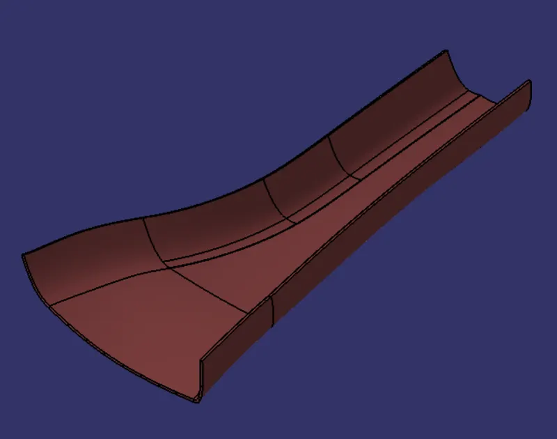
Figure: Final Closed surface
- Switch to the Part workbench, then apply the closed surface command on the final closed surface to create Final Closed body.
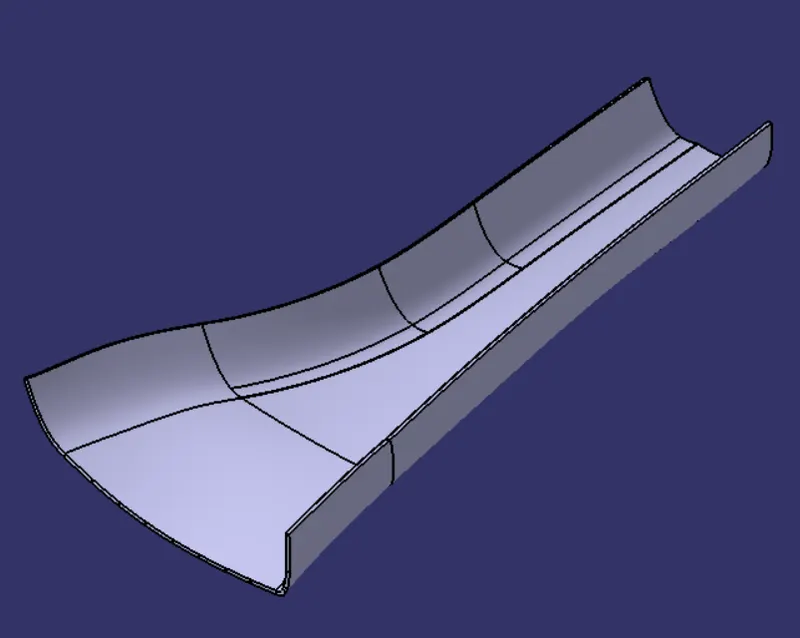
Figure: Final Closed A-pillar body
Draft Analysis on Final Closed Surface
- Change the view mode of the component to be in customized parameter mode and then select the shading mode as materials.
- Using the "Draft analysis" command, click on the compass to define the current drafting direction and lock the compass on the tooling axis and perform the draft analysis by clicking on the Closed body.
- Click on the analyses under the running point to check the draft analysis on the individual faces. It shows how much draft on specific points when we move the cursor point.
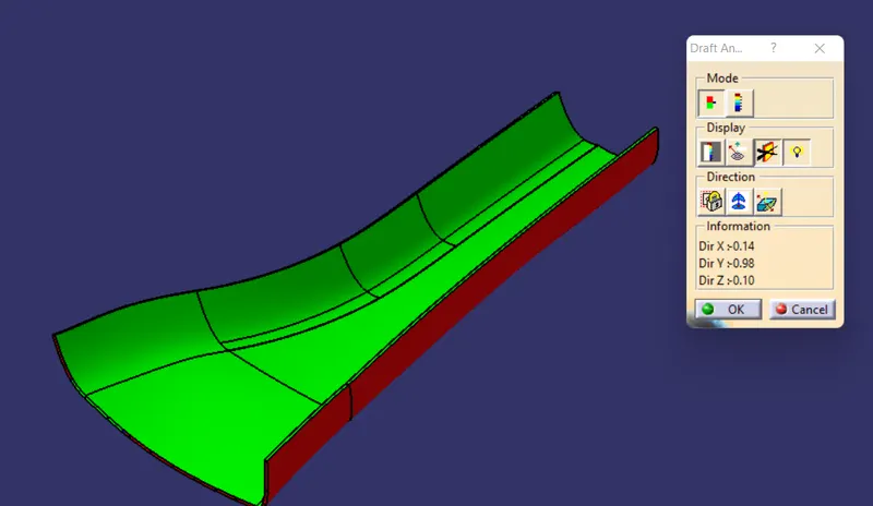
Figure: Draft analysis on Final Closed body.
Creation of Doghouse:
- The Doghouse on the A-pillar is crearted with the help of the given matersection.
- From the given mastersection, the inside side walls line are extracteed using the Extract Command. Further, these extracted lines are extruded.
- Similarly, the upper inside wall are extracted and extruded from the mastersection.
- Next, the back wall line are extracted from the given mastersection and extracted.
- Further, all the extracted surfaces are trim along to get proper Doghouse structure
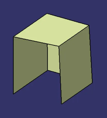
Figure: Doghouse extruded structure
- Next, switch to the part workbench and using the Thick surface command, thicken the extrapolated surface to 1.5mm offset outside.
- Further, side lower core are trimmed from the Doghouse partbody.
- Similarly, the rib lines are extracted and extruded and these surfaces are thickend to 1mm
- Next, draft of 0.5 degrees are provided on the outer faces of the Doghouse in the direction of Tooling axis
- Another draft is created on the inner faces and the ribs of the Doghouse in the direction of the Side core axis.
- Finally fillet is provided on the required outer and inner faces of the Doghouse.
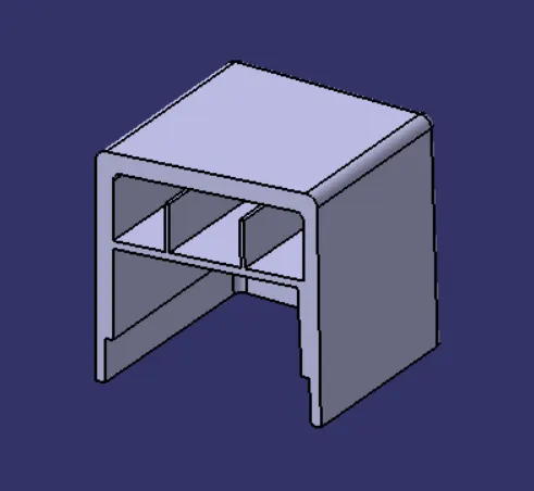
Figure: Doghouse
Draft Analysis on Doghouse:
- Further Draft analysis is provided on the Dog house by aligning the compass on the Tooling Axis
- Change the view mode of the component to be in customized parameter mode and then select the shading mode as materials.
- Using the "Draft analysis" command, click on the compass to define the current drafting direction and lock the compass on the tooling axis and perform the draft analysis by clicking on the Closed body.
- Click on the analyses under the running point to check the draft analysis on the individual faces. It shows how much draft on specific points when we move the cursor point.
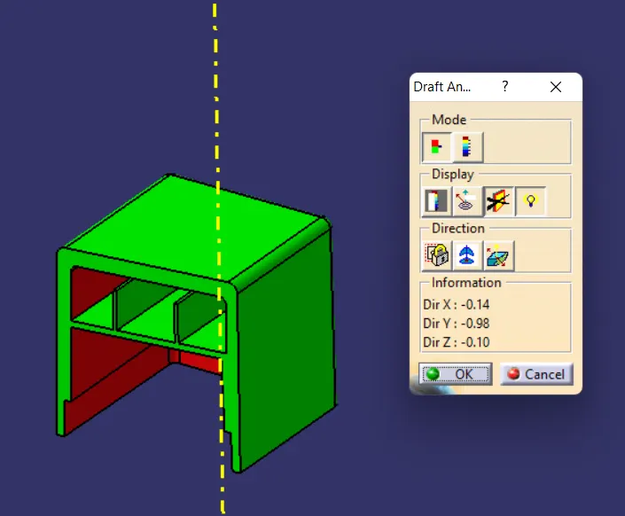
Figure: Draft analysis on the Doghouse along the Tooling Axis
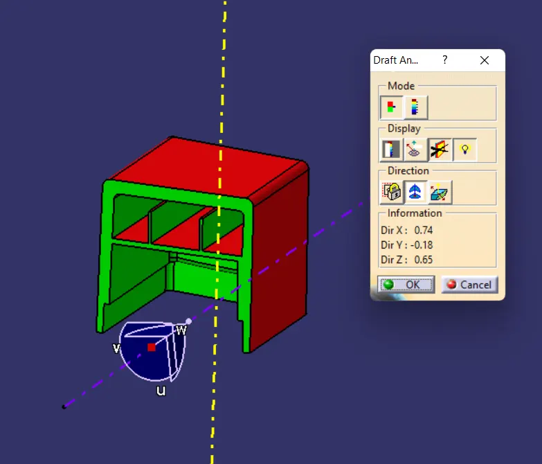
Figure: Draft analysis on the Doghouse along the Side Core axis
Final A-pillar with Doghouse:
- Next, the Part body of the A-pillar is defined and Doghouse part body is added on it usinf the Union Trim Boolean operation.
- Further Draft analysis is performed on the Complete Part body.
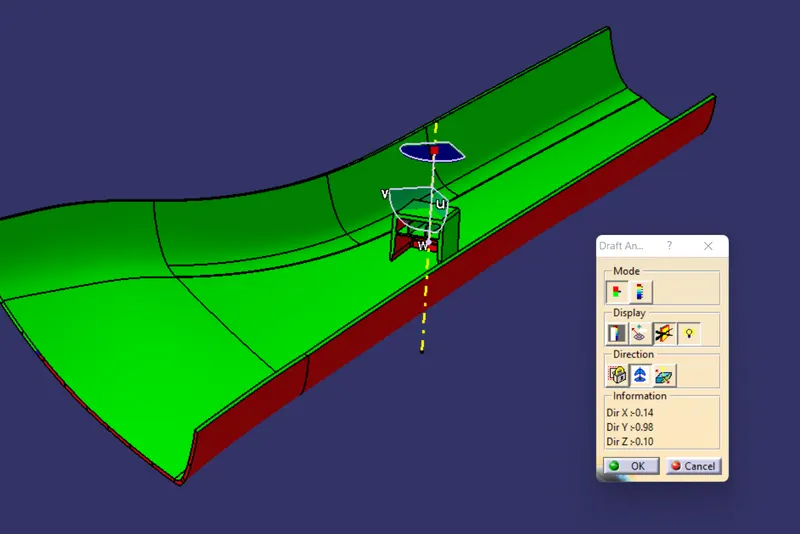
Figure: Draft Analysis on the A-pillar with Doghouse.
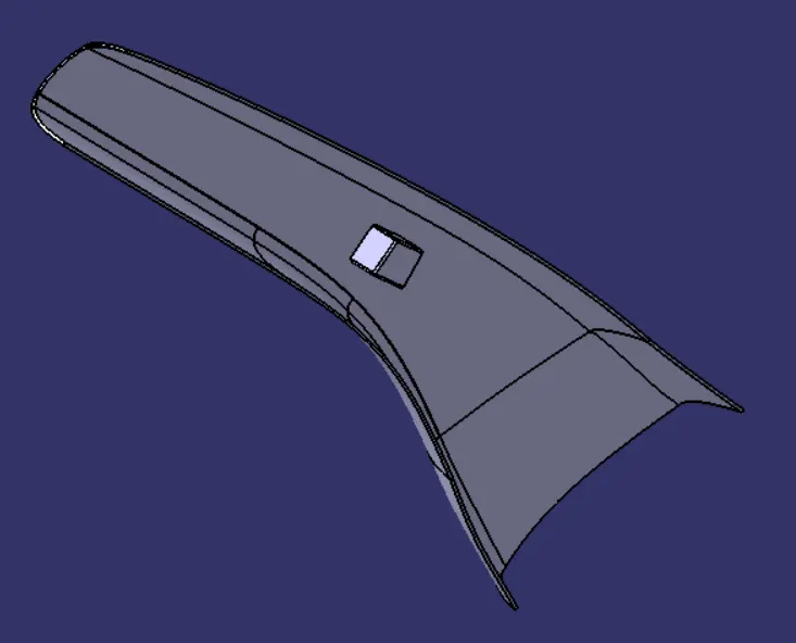
Figure: Isometric View of the Partbody
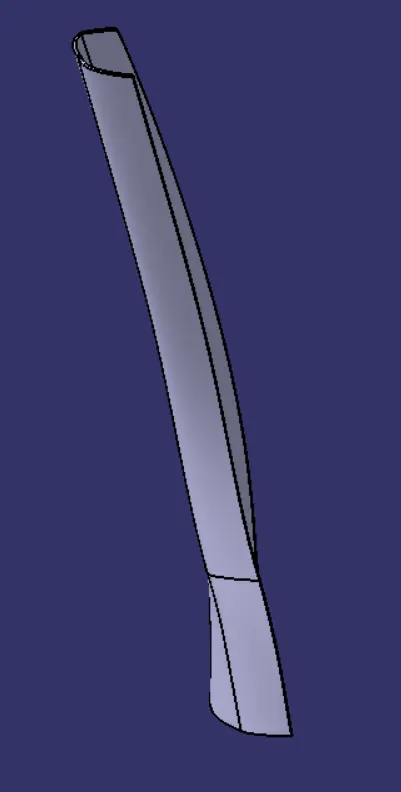
Figure: Front View
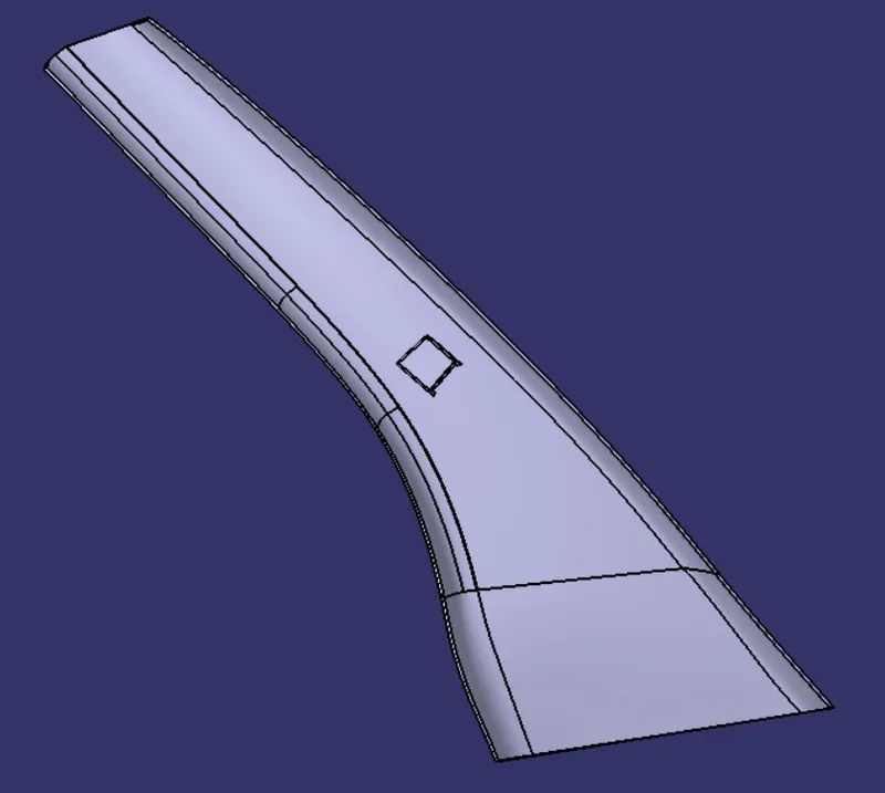
Figure: Side View
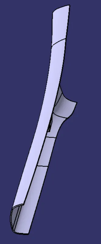
Figure: Top View
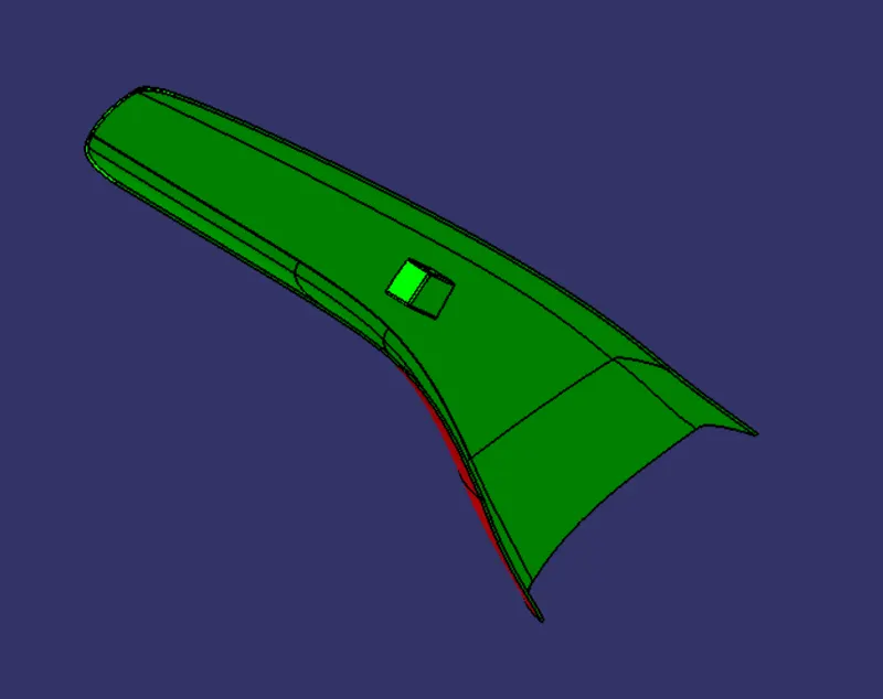
Figure: Isometric View
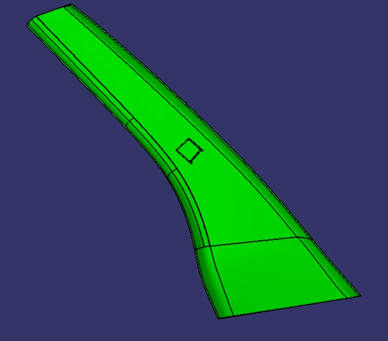
Figure: Side View
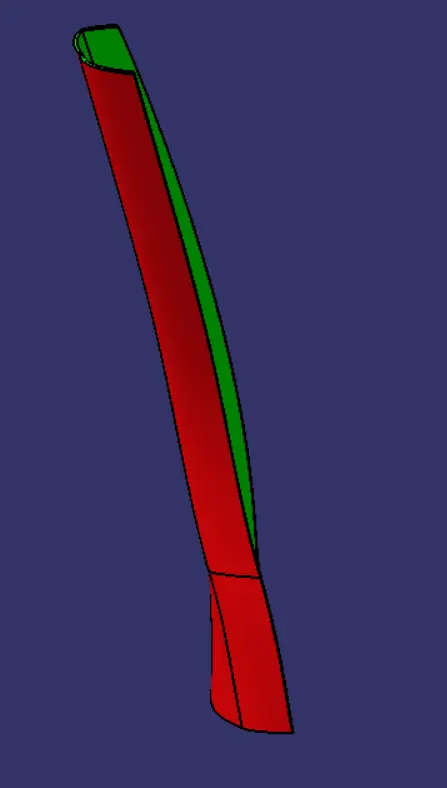
Figure: Front View
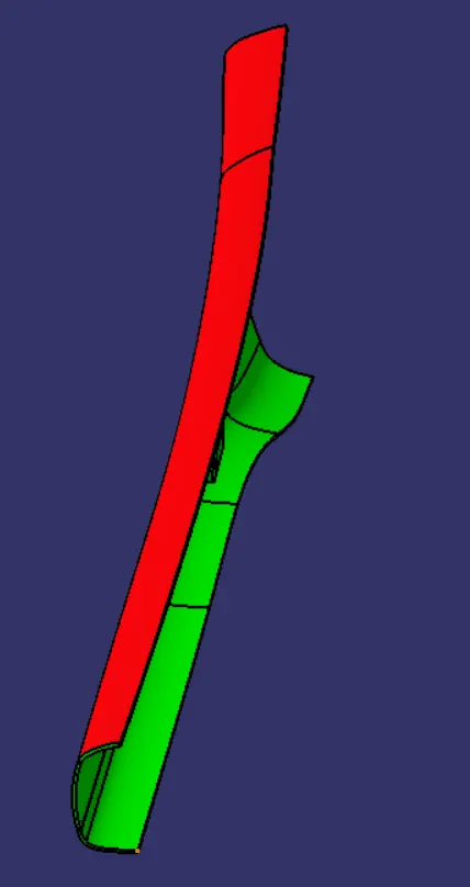
Figure: Top view
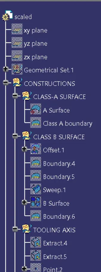
Figure: Expanded Tree -1
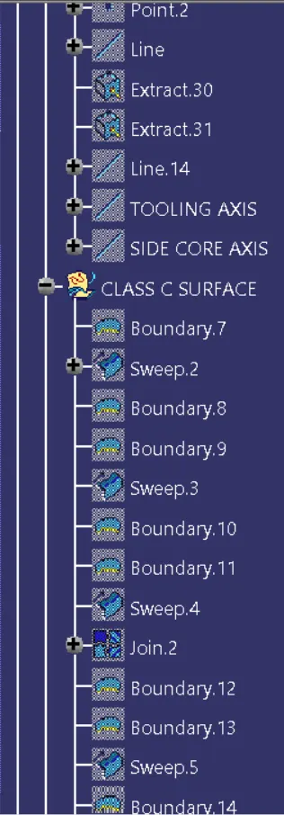
Figure: Expanded Tree - 2
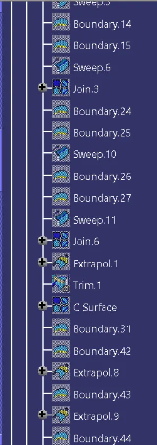
Figure: Expanded Tree - 3
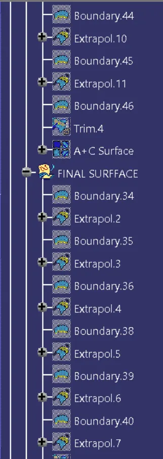
Figure: Expanded Tree - 4
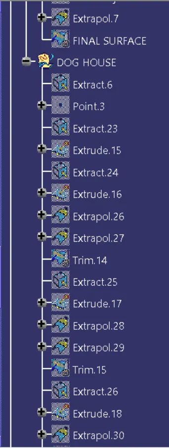
Figure: Expanded Tree - 5
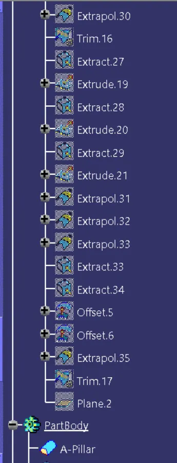
Figure: Expanded Tree - 6
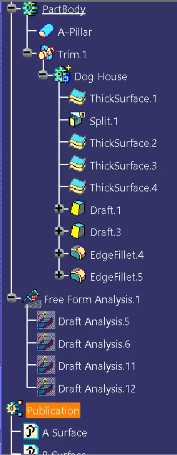
Figure: Expanded Tree - 7
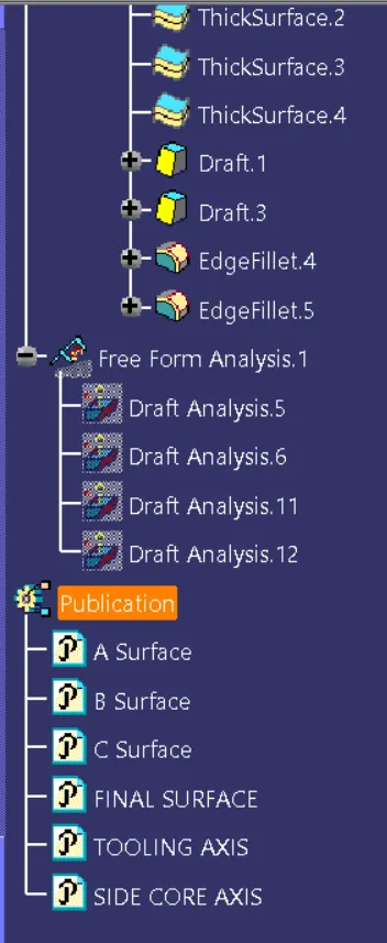
Figure: Expanded Tree - 8