Week 9 - Project - A pillar Design with Master Section
Input
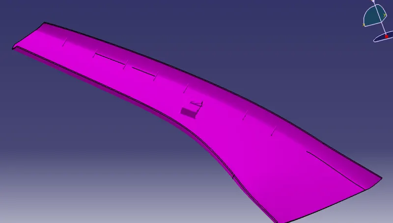
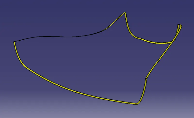
Class A Surface with master Section
Tooling Axis
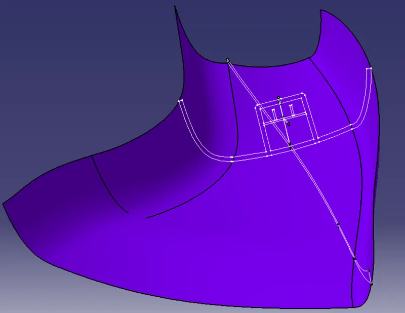
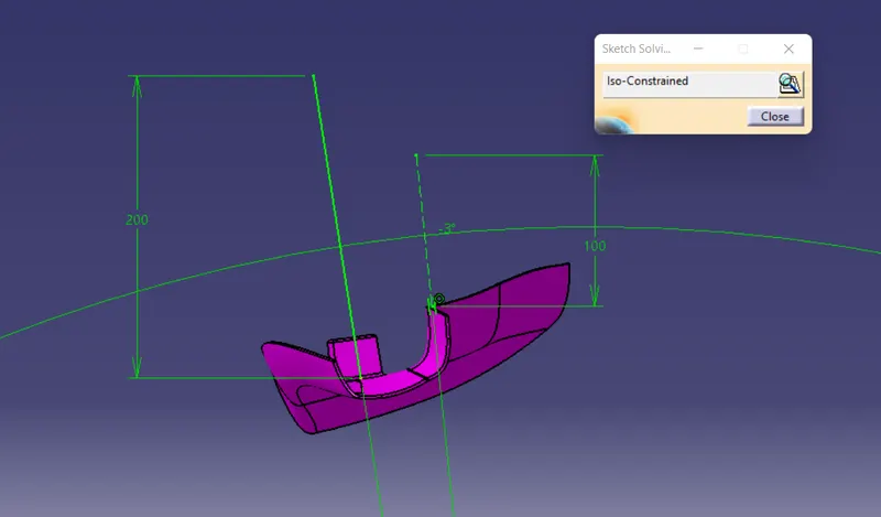
The tooling axis is the direction along which the core moves. While designing the model it is to ensure that all the surfaces should have a minimum draft of three degrees with the tool axis. The tool axis is created by using the bisecting line method.
Main Tool Axis
Side Core Axis
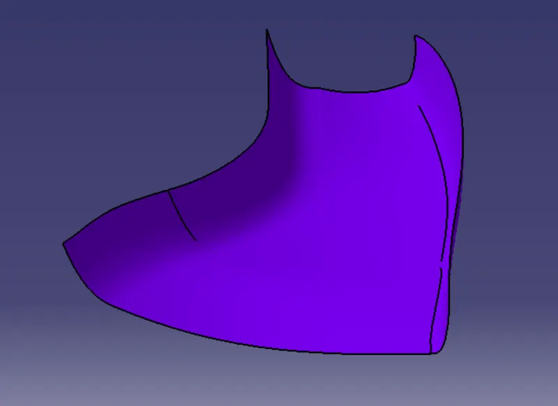
Class-B-Surface
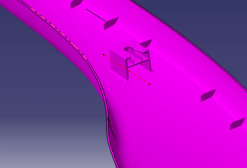
The class B surface is created by offsetting the class A surface.
Class-C- Surface
The class C surface is the surface that connects the class A and class B surfaces.
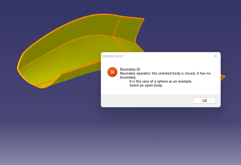
The Closed Surface Model
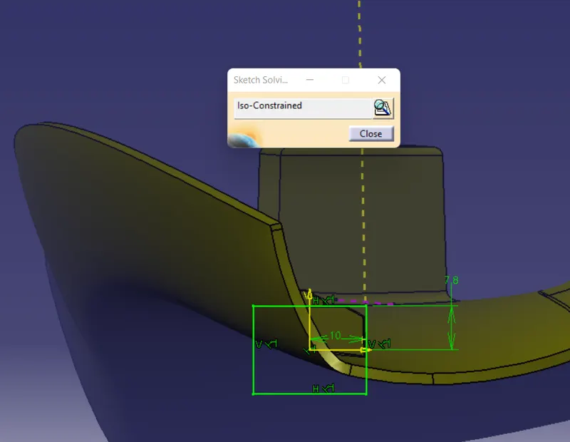
Sketch Status
1)
2)
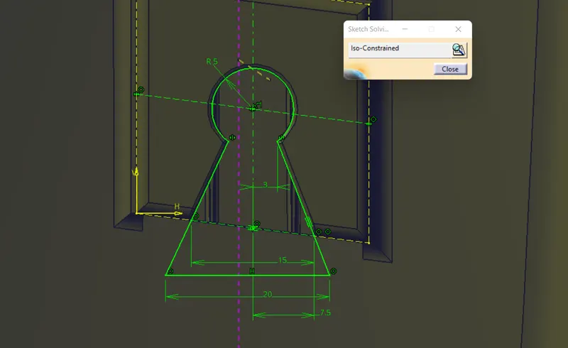
3)
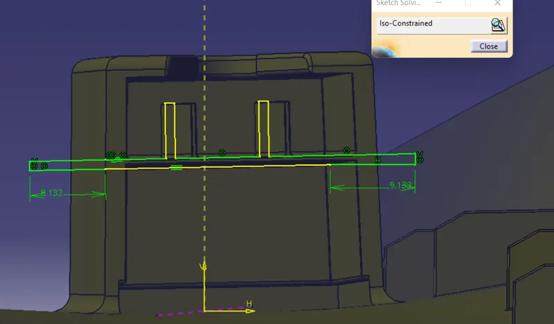
4)
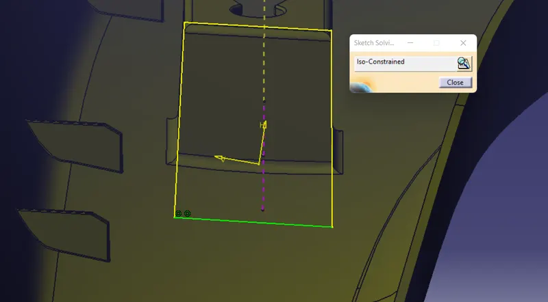
5)
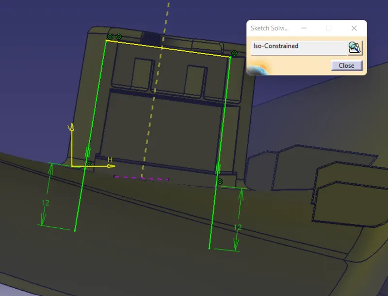
6)
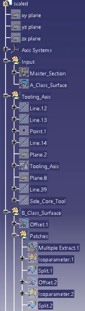
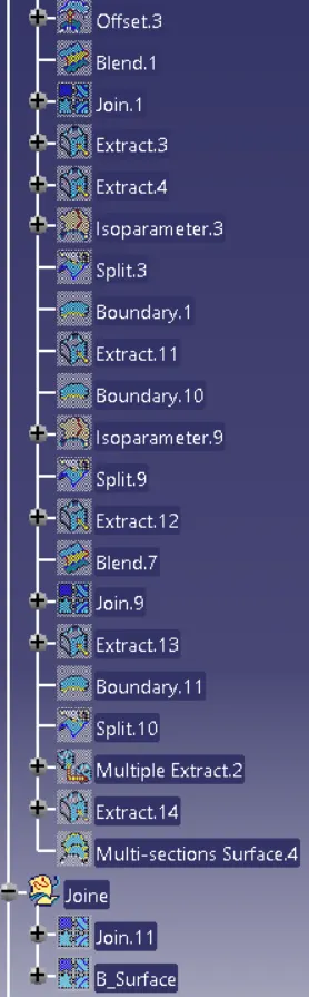
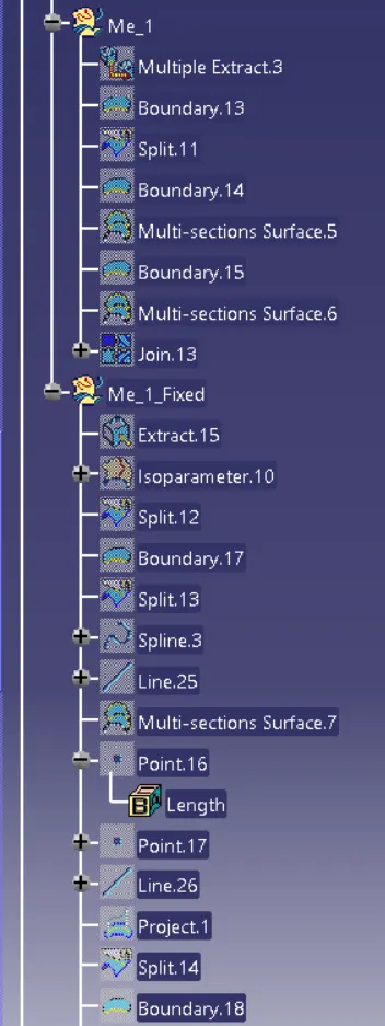
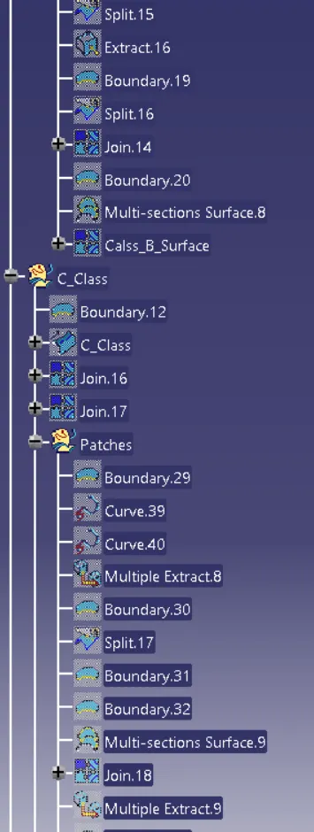
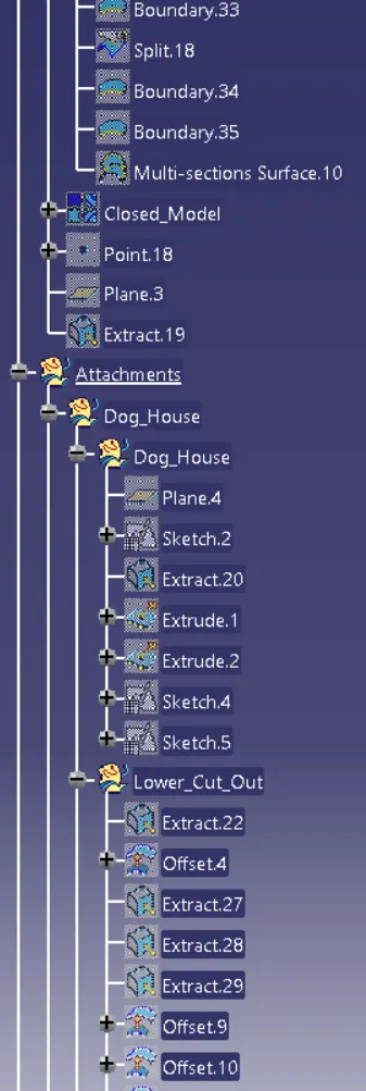
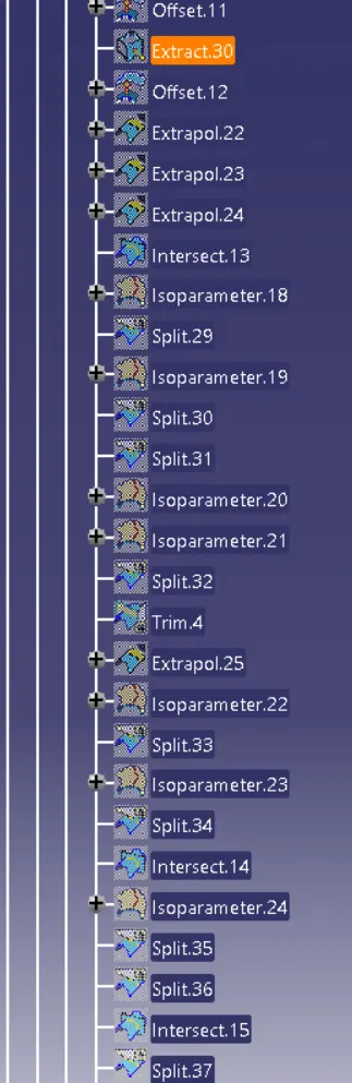
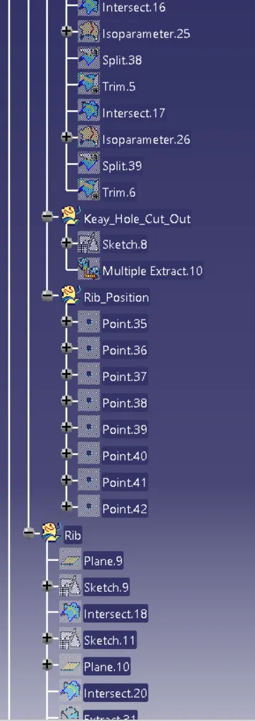
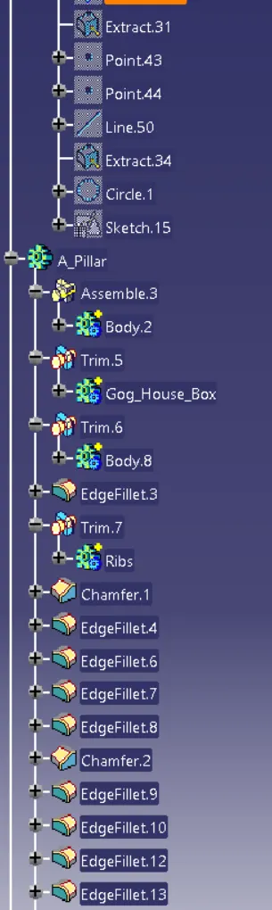
Feature Tree
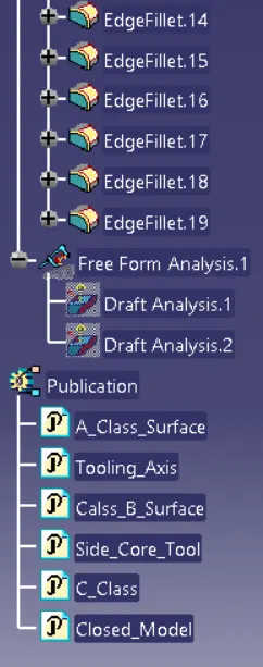
Draft Analysis
Draft analysis is conducted to ensure that all the surfaces maintain the minimum draft angle.
Draft Analysis Along the Tool Axis
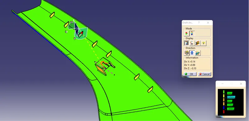
Most of the surface maintains the 3-degree draft, and all the attachment features maintain a minimum of 0.5 degrees draft with the main tool axis.
Draft Analysis Along The Side Core Axis
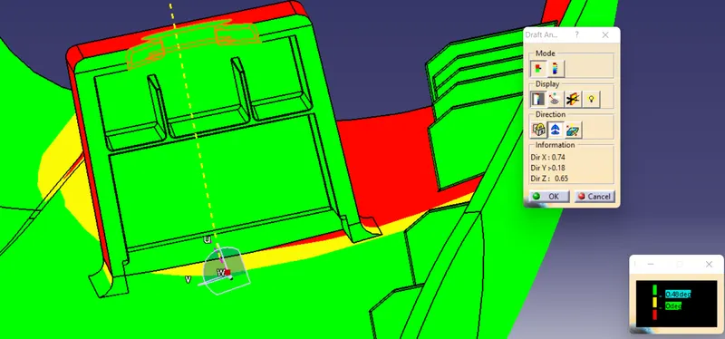
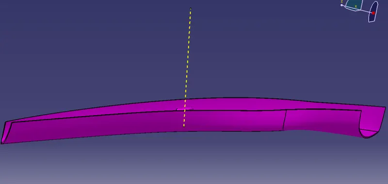
The sire core axis is used to conduct the draft analysis over the dog house to make sure all the surfaces maintain a 0.5-degree draft. There is an error of 0.02 on some axis, but all the surfaces clear the minimum requirement.
Model View With Master section
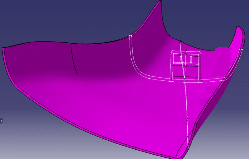
Standard Views
Front View
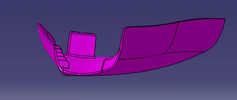
Side View
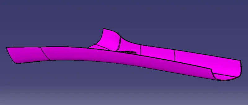
Top View
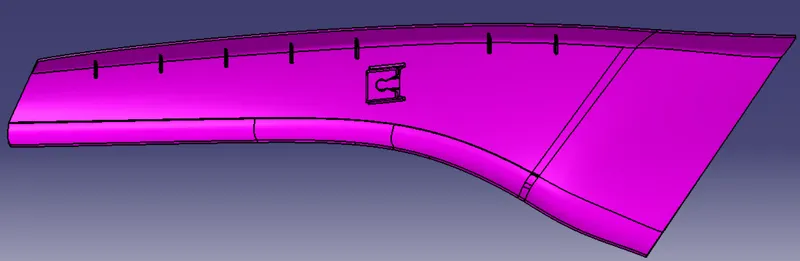
Isometric View