Week 9 - Project - A pillar Design with Master Section
- AIM:- TO CREATE A PILLAR DESIGN WITH MASTER SECTION.
Given Data:-
- Class A Surface
- Master Section
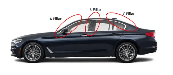
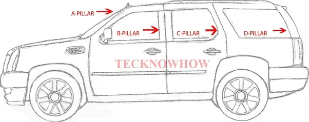
- A Pillar:- The A pillar is the frame of the windshield that is between the windshield & the front doors.All cars with a windshield come with an A pillar.The B pillars are located behind the front doors.It is the frame between the front & rear doors.
The naming system adopted for the pillars possibly originates from their shapes as seen from sides as shown in fig. The A-pillar resembles the shapes of the aphabet "A".The other pillars resembles "B","C", & "D" letters,respectively.
- Master Section:-
Master sections are the guides for the design requirements which shapes the component after technical styling of class A surface.Master sections are parametrised model of the vehicle body that outlines the guide for NPD team.
In this report A pillar cover creation with detailed procedure of surface development & attached features are coverd.
- Class A Surface:-Styling surafce that is visible to the customer & gives as aesthetic lookfor the model designed.It has curvature conyinuity.
- Class B Surface:-It is the secondory surface where all engineering features like Dog house,ribs,flanges,locators,etc. are included.This is the direct offset of the class A Surafce which gives thickness to component.
- Class C Surface:-This surface is a combination of class A & class B surface also they are the backside surface that can have tool marks,falsh & other defects without touching appearance.
- Methodology for cration of A-pillar in detailed-
- Master section_1
- Master section_2
- Class A surface
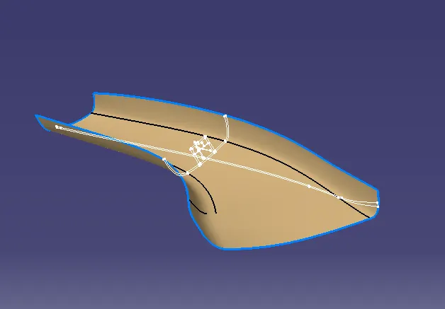
Step 1:- To ensure that the class A surafce is properly joined or there is any discontinuity in the model.This can be checked by using two options,join or boundry feature in CATIA.
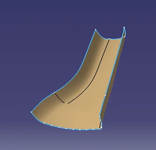
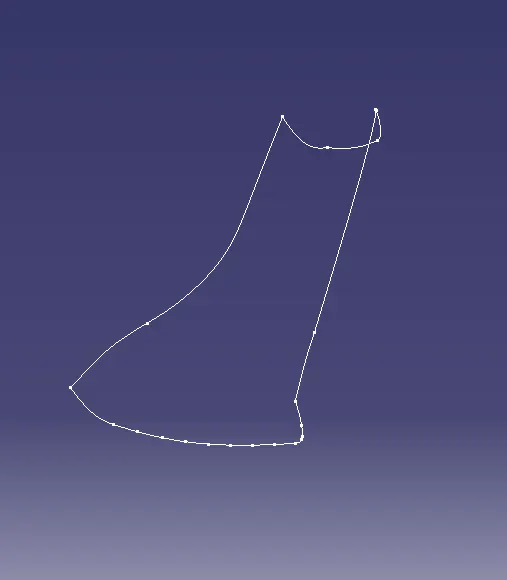
In above fig we can clearly see that there is only one boundry,so we can proceed for further steps.
Here, in this case I need to improve class A by removing one patch so that it is to create Class B.
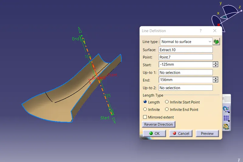
- Tooling Direction:-The Tooling direction is basically the direcction that the mold pulls apart.The mold is built in two seperate pieces, basically we have a cavity side and core side. The core pulls apart from the cavity abd taht's the Tooling direction. I have created here Tooling axis about NORMAL TO SURFACE.
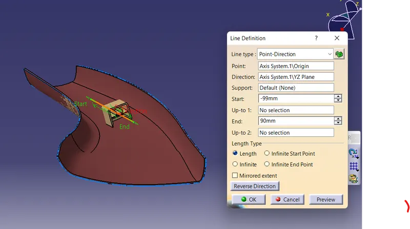
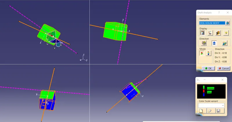
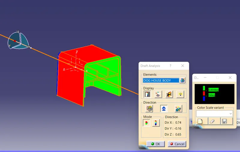
- Side Core Axis:-The main purpose of creating the side core axis is to clear the inner surafces of dog house & Ribs.
- Draft Analysis:- Draft analysis is required to check if a part has required draft or not.Necessory draft angle is required to ensure that a part can be ejected from its mould or not.Generally we give draft as 3degree.Draft angle may varry according to surface we create.
Draft analysis on class A Surface
To check the validity of Tooling axis,draft analysis is performed on class A surface.Draft analysis result shows that the plastic product which is drafted to desired nominal angle for feasible clearance and ejection of final part from the mould.
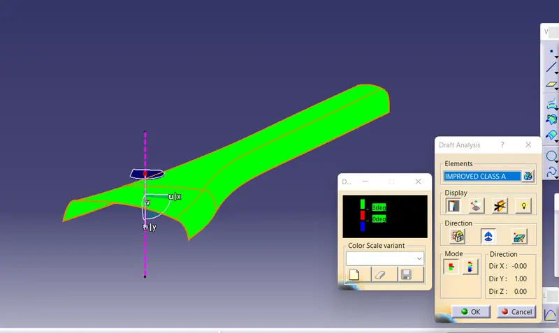
From the above fig. of draft analysis results, it was observed that all surfaces fullfill the condition of `3 degree` positive draft.
Class B surface Creation:-
As the given class A surface is a complete styling surface & does not have any defined fillet values or intersection.To get the class B surface,there are two ways-
1.Simply the complete class a surafce offset at distance.
2.Extract flat surface & work them one by one.
Class C surafce creation:-
For creation of class C surface,all edges of the class A are extracted & given sweep operation with reference to surface.
Creation of surface model:-
Firstlly joined class A+C & trimmed with B.Closed volume is formed without open boundary, and this is our Surface model.
Creation of Closed Body:-
Closed Surface model is converted into solid closed body using part design workbench.
B SIDE FEATURE CREATION:-
1.DOG HOUSE WITH RIB:-Dog house is an engineering feature used on B side to incerased the length of screw bossor Locators.This allows to have a long attachment feature with better strength & no sink marks.
2.Ribs:-Ribs are the supporting members which prevents the bending of surface & provide strength to the component.
Here, I have taken reference of master section to craete Dog house n Ribs.
Perform Draft analysis on fianl model:-
Draft analysis is performed on the final componnet to check its manufaccturing ability.Draft analysis is performed using main Tooling axis.
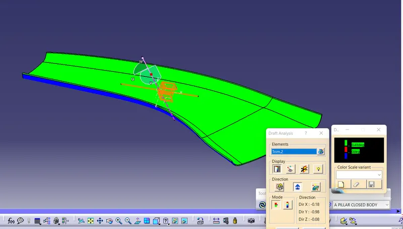
All faces of class A surface of component are positive except some patch area.
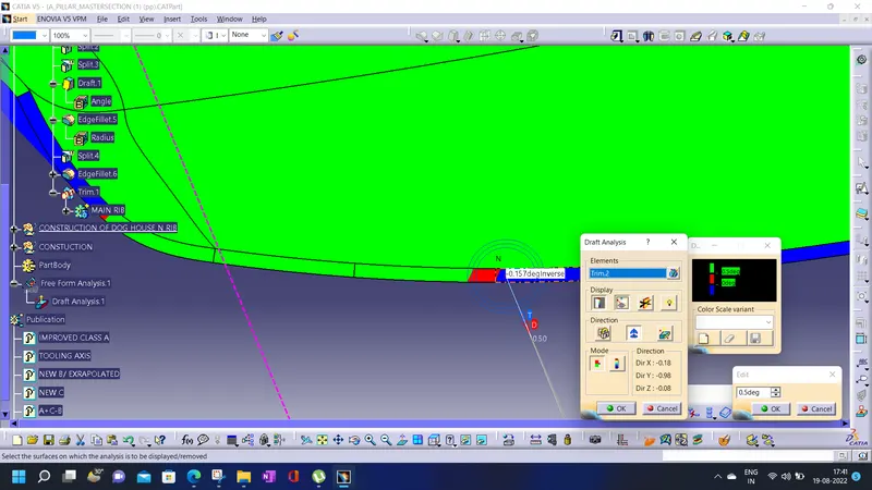
Draft analysis on Dog House & Ribs:-
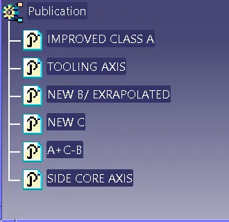
Publication:-
CONCLUSION;-
The design of A-pillar is completed & from draft analysis,it is observed that the design is safe to manufacture except some imperfections which will be communiated to class A team.