Week 9 - Project - A pillar Design with Master Section
OBJECTIVE: To design a with Master Section.
INTRODUCTION
During the stages of the product life cycle known as feasibility check and concept validation, the development of master sections takes place. These are the common guides that are used for design requirements, and following the development of the concept design, they are the ones that decide how the component packaging should look, i.e. class A surfaces.
Before transforming the concept design into a real 3D engineering design, the master section assists us in deciding the viability of the concept design, as well as the clearances, the packing, and the fixation strategy of a component.
When it comes to the evaluation of the master section performance during the phase of vehicle concept design, the most important factors to consider are the reference vehicle data and the experience of the structure design engineer.
CREATION OF THE CLASS B SURFACE
Because the A PILLAR needs to have a thickness of 2.5 millimetres, we will need to give the improvised class A surface an offset value of 2.5 millimetres in order to generate the class B surface.
When we apply the offset command, we will notice that some of the patches of the resulting surface do not generate. Because of this, we will need to use the multi-section surface command to rebuild those patches.
We will have the class B surface after we have joined the newly constructed patches with the previously offset surface.
OBJECTIVE: To design a with Master Section.
INTRODUCTION
During the stages of the product life cycle known as feasibility check and concept validation, the development of master sections takes place. These are the common guides that are used for design requirements, and following the development of the concept design, they are the ones that decide how the component packaging should look, i.e. class A surfaces.
Before transforming the concept design into a real 3D engineering design, the master section assists us in deciding the viability of the concept design, as well as the clearances, the packing, and the fixation strategy of a component.
When it comes to the evaluation of the master section performance during the phase of vehicle concept design, the most important factors to consider are the reference vehicle data and the experience of the structure design engineer.
CREATION OF THE CLASS B SURFACE
Because the A PILLAR needs to have a thickness of 2.5 millimetres, we will need to give the improvised class A surface an offset value of 2.5 millimetres in order to generate the class B surface.
When we apply the offset command, we will notice that some of the patches of the resulting surface do not generate. Because of this, we will need to use the multi-section surface command to rebuild those patches.
We will have the class B surface after we have joined the newly constructed patches with the previously offset surface.
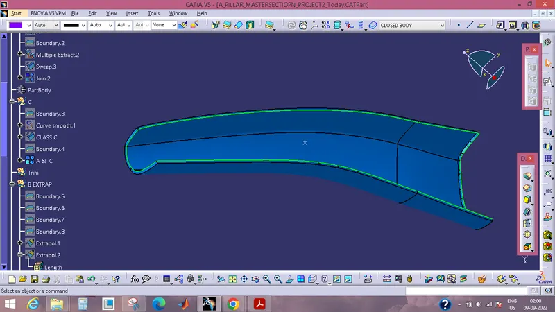
CREATION OF THE CLASS C SURFACE
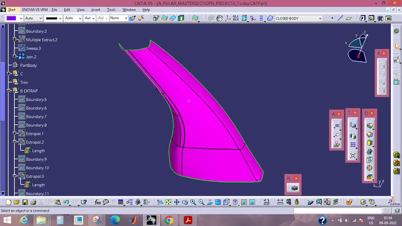
The enhanced class A surface should have its side edges, front edges, and rear edges extracted, then the sweep command should be used with the "with refrence to draught" option and the draught angle should be set to three degrees.
Use the multi-section surfaces command to construct surfaces that are lined with the primary surfaces that were formed during the sweep operation for the remaining edges.
Apply the JOIN command to all of the surfaces to CONNECT them together.
CLASS A & C JOIN
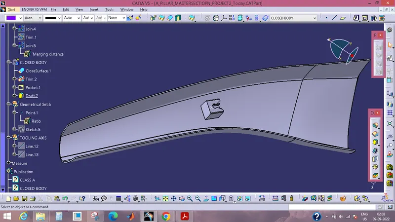
THE FORMATION OF THE SOLID BODY OF THE A PILLAR
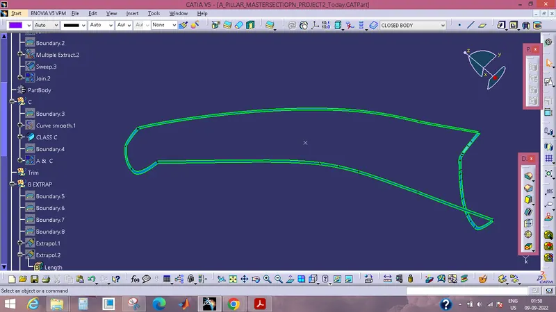
Combine the class A surface and the class C surface by applying the Trim command. Cut away the excess class C surface from the resulting trimmed surface. The closed shell body of the A pillar will be the trim that we acquire as a result of this process. Use the closed surface command in the part design workbench to turn the shell body into a part body at the very end.
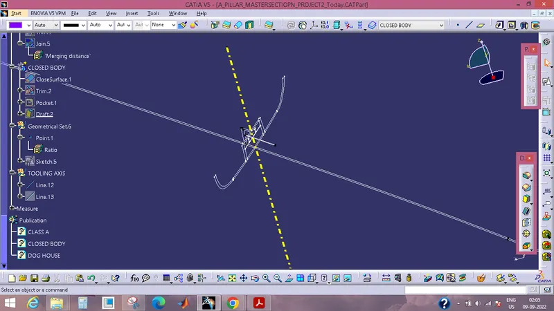
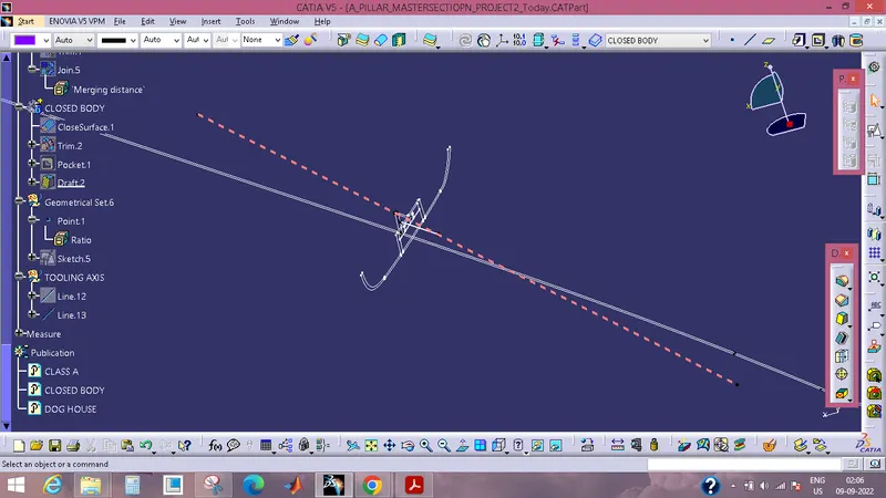
TOOLING AXIS GENERATION FOR BOTH THE MAIN AND SIDE CORE
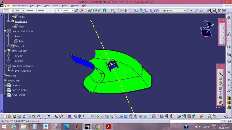
Because all attachment features have a large number of surfaces that are parallel to the tooling direction, in addition to the A surface and the C surface, we also need to consider the B side attachment features in order to create the tooling axis. This is because the A surface and the C surface are not the only two surfaces involved.
DOG HOUSE & RIBS
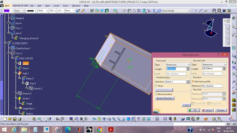
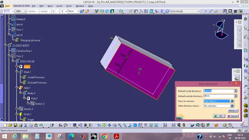
Create the dog house & ribs as per master section.
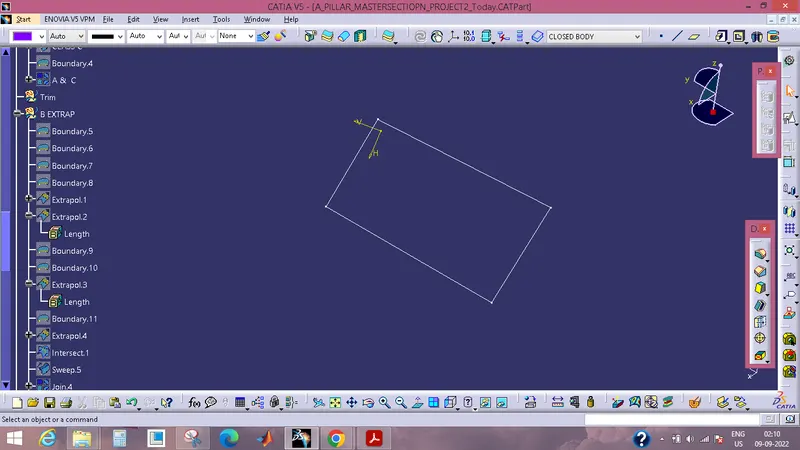
PAD IT NOW
SHELL IT DEFINING 2.5 MM THICKNESS
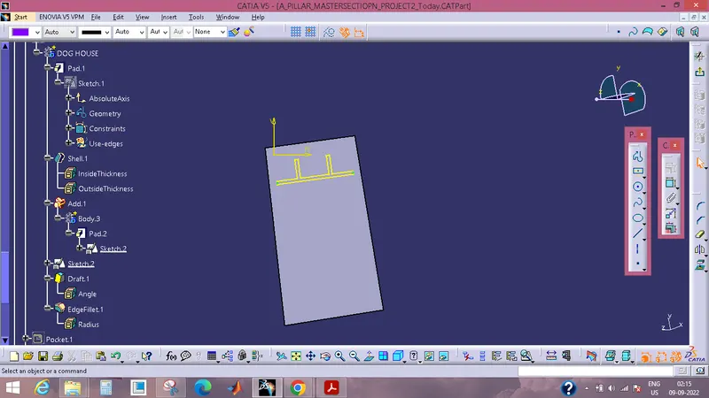
GIVE DRAFT TO RIBS
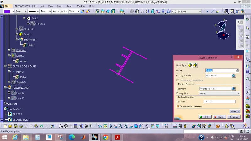
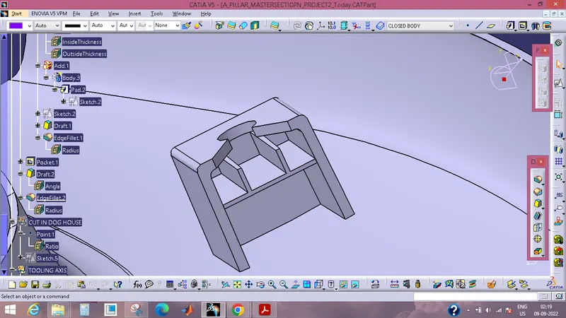
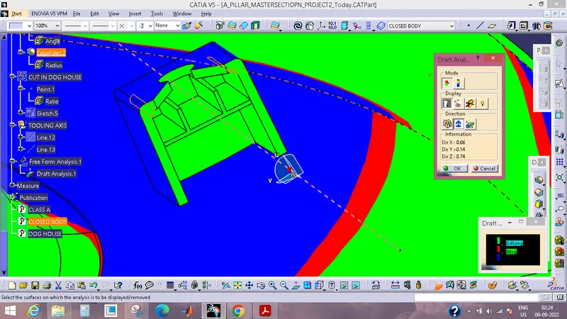
DRAFT ANALYSIS ALONG MAIN AND SIDE CORE