Week 8 - Challenge 2 - Switch Bezel Design
Aim:
To construct the Switch Bezel plastic component using the provided class A surface, as well as to produce the necessary Tooling axis and carry out a drafting analysis on the model.
Objective:
First, you will need to generate the requisite proper Tooling axis, and then you will execute the Draft analysis on the class A surface that has been provided. By utilising the surface modelling tools, you may create the class-B surface as well as the class-C surface. Additionally, the closed surfaces of classes A, B, and C should be combined into a single solid body. In addition to this, carry out the Draft analysis on the solid model.
Theory:
The Tooling Axis is as follows:
In injection moulding, the Class-A surface is initially evaluated to determine the tooling axis, also known as the tooling direction, along which moulds pull apart. Tooling direction is critical for the design of plastic products because it determines the path that mould separation will take.
The following procedures were carried out in order to create the tooling axis:
On the surface that has been removed, a reference point is initially constructed.
In order to plot clearance lines, a new axis system has been deployed.
In order to establish the tooling axis, the X-direction and the Y-direction along the class-A were used.
The tooling axis was formed by cutting through the middle of two clearing lines.
Prior to publication, alterations were made to the graphical features of the tooling axis.
Draft Analysis:
For moulded or cast pieces, the degree of taper that runs perpendicular to the parting line is referred to as the Draft angle. The temperature can be expressed in degrees. In order to decrease the possibility of the parts being damaged and to guarantee their ejection, a functional part for injection moulding needs to have draughts facing both the cavity and the core sides. In order for the part to detach from its housing in the correct manner, it is essential to beat the vacuum forces by allowing air to enter the space between the metal and the plastic. incorporating while keeping a respectable cosmetic appearance. For both the production and the plastic product, there should be a draught included in the design. At the very beginning of the design process, the designer ought to be aware of its necessity. Because of this, design requirement factors can be taken into account.
Nominal values for Draft angle:
The Draft angle is generally considered to be 3 degrees. 7 degrees for a surface with a texture. Producing an angle of at least 0.5 degrees requires the use of specialised equipment. However, this will result in a rise in the cost of production.
Creation of the tooling axis: The first thing to do is make a careful observation of the class-A surface that has been provided to you, and we can identify the larger flat area that runs perpendicular to the Tooling axis. When taking all of this into consideration for this class-A surface, the tooling direction is relatively close to the Z-axis. Therefore, we mark off the place on the ground using the diagram as our guide.
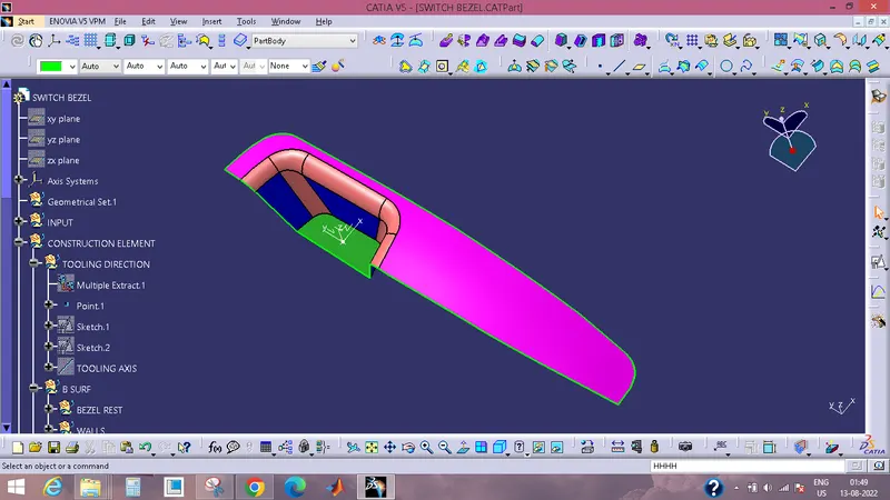
The next thing you need to do is make the reference axis out of the X-axis and the Y-axis. Therefore, in order to accomplish this, we will be using the two side flat surfaces as our reference. Next, we will use the intersecting line tool in order to draw lines along the faces in the Y-direction. Finally, we will use the bisect line tool in order to draw the reference axis in the Y[1] direction, as shown in the figure.
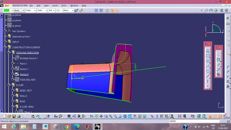
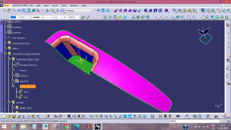
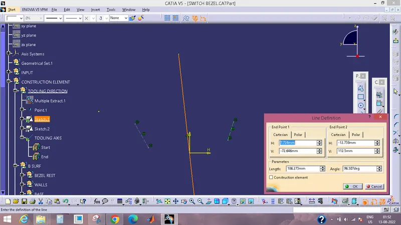
The next step is to construct the reference axis using the x-axis as a starting point. In a similar manner, the reference was obtained from the X-direction, as illustrated in figure. Now that we have both direction reference lines, the following step is to establish the primary tooling axis. In order to accomplish this, we will build the surfeit along both reference lines, as shown in the picture. And by using the definition of an intersection, we were able to derive the primary tooling axis, which is depicted in the picture.
Procedures carried out for the Draft Analysis:
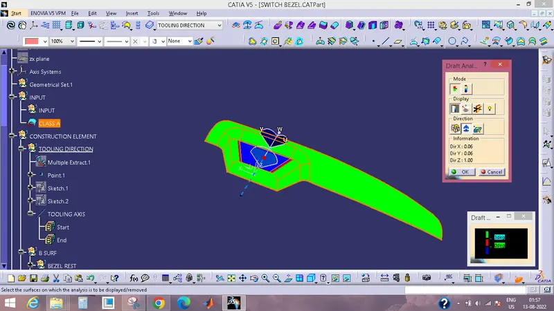
- It is necessary to switch the newly formed part over to the material mode in the display frame.
- Compass is turned on, and you should position it so that it points in the same direction as the tooling.
- After then, the Lock command is used to fix the compass in addition to the tooling axis.
- There is a classification of colour codes, and the draught angle is applied.
- Running point analysis is what's used to show what the allowed draught angle is.
Surface classification A:
The category- A surface is the outermost surface of the plastic component, which is also the surface that appears fine. The designer generates the aesthetic surface as an input portion for the design process, and it is the surface that is being referred to here.
Class B surface, sometimes known as
Class B is the offset of 2.5 millimetres from the surface of class A; nevertheless, the fillets on the surface of class A may produce an error if we directly offset the surface of class A. I removed the bezel rest surface, as well as the walls and the base of the surface, so that I could correct those faults. Now, we need to trim those extracted surfaces to get them into the same shape as a class-A surface, so we need to untrim them and then extrapolate to get planes to intersect with each other. After offsetting the trim by a distance of 2.5 millimetres on the reverse (or lower) side of the class A surface, I give the fillets to the edges while keeping the thickness in mind.
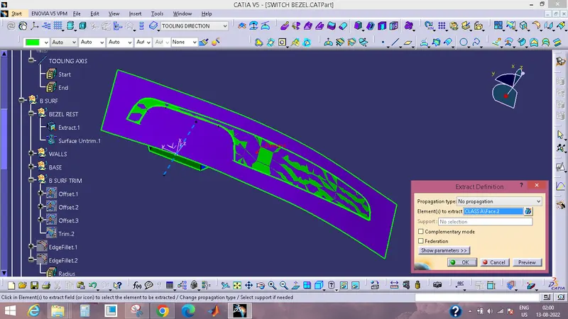
Bezel rest surface

Final Trimmed and Filleted Class B surface:
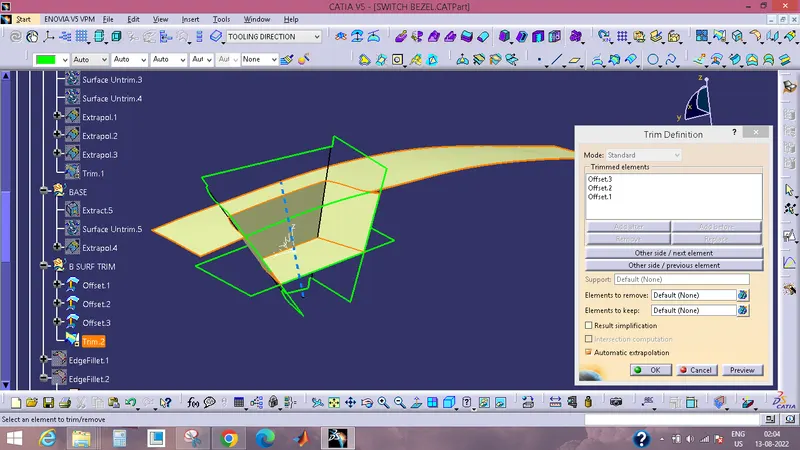
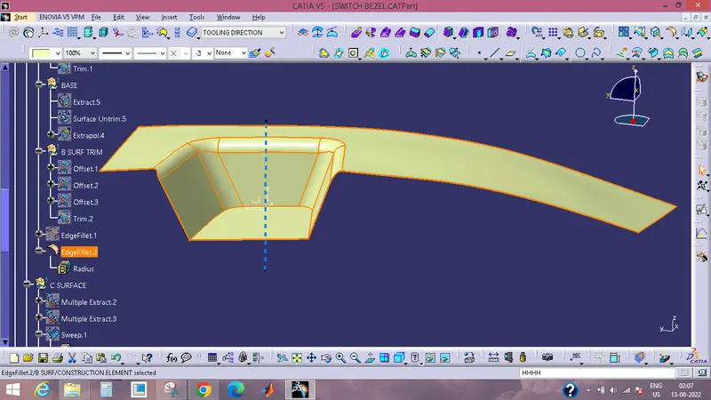
A SURFACE OF CLASS C:
Class C surfaces are those that are created by combining Class A and Class B surfaces. Using the multiple extract command allowed me to extract the border of the class A surface, which I then used to create the class C surface. Now, using the sweep command with a drafts angle of 3 degrees, expand the class A surface border that was previously drawn. After I had combined class A with an extended surface, I proceeded to trim the surface that I had just joined with a class B surface so that I could obtain a closed body.
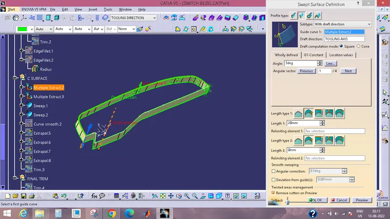
FINAL TRIM:
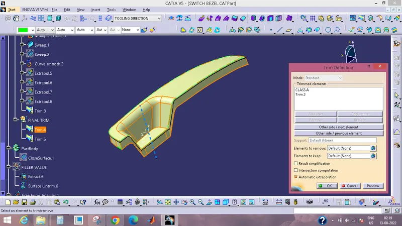
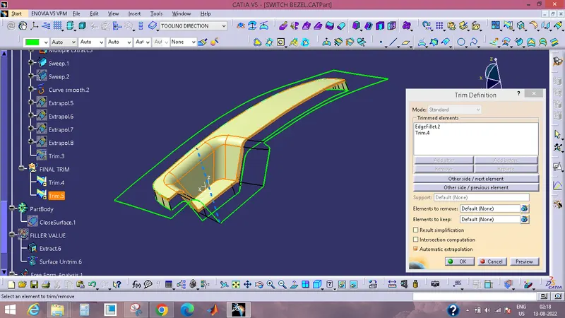
PART BODY:
After constructing a closed body, the next step is to construct a solid body by using the closed surface as a starting point. Proceed now to the part workbench in order to create the sloid body by utilising the closed surface command.
DRAFT ANALYSIS:
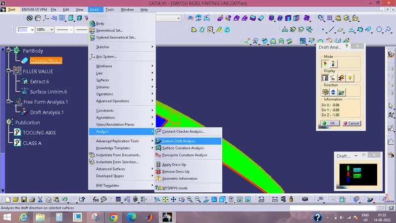
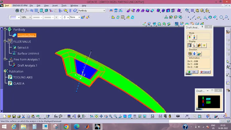
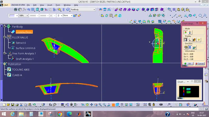
The highlighted drafting analysis command is used to do the drafting analysis once the development of the solid body has been completed. Simply click on the compass icon, and then drag the compass till it is aligned with the tooling. if the surface is a green colour, the drafting angle is larger than 2.9 degrees (the limit for the green colour is 2.9 degrees), and if the surface is a red colour, the draught angle is less than 0 degrees.