Week 9: Project 1 - Surface preparation and Boundary Flagging (PFI)
AIM: Surface preparation and boundary flagging of port fuel injection engine.
OBJECTIVE:
- Bondary flagging
- surface preparation
INRODUCTION:
- PFI system replaced carburetter in cars because of their efficiency and lower maintenance requirements.
- In port fuel injection (PFI) or multiport fuel injection (MPFI) fuel is injected into the intake port of each combustion chamber via a injector.
- With PFI, gasoline is sprayed into the intake manifold, wher it mixes with air and then is sucked down into the cylinders.
Boundary flagging
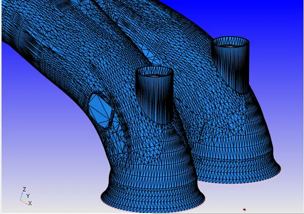
exhaust port
intake port
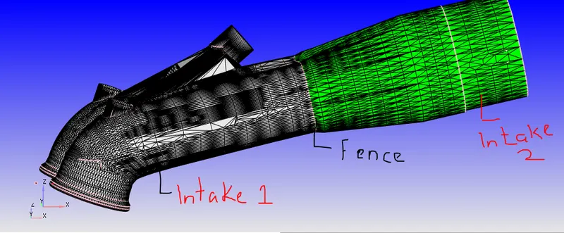
intake port1 (near to combustion chamber) and intake port2(near the inlet)
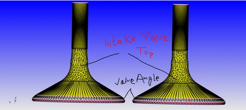
intake valve top
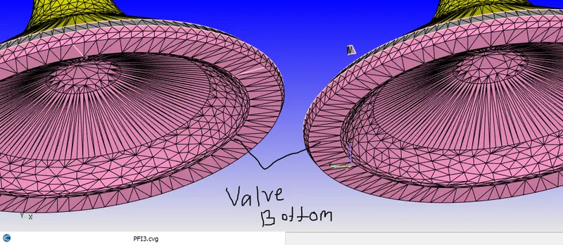
intake valve bottom
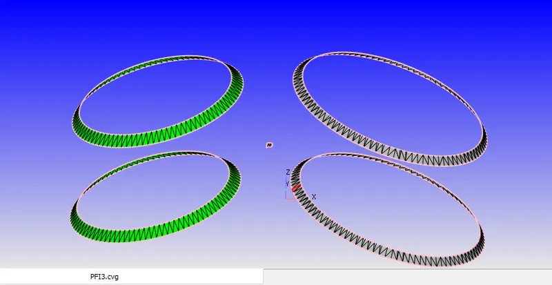
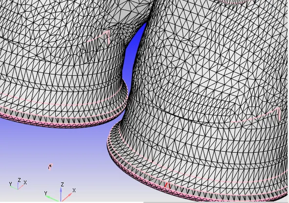
valve angle
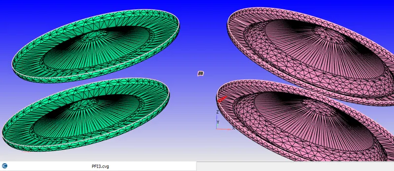
valve bottom
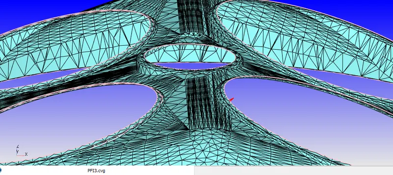
cylinder head
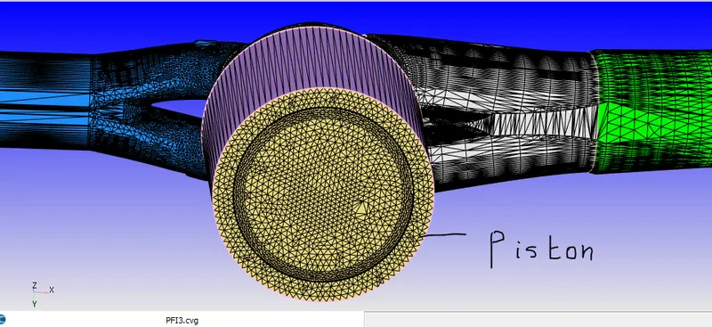
piston
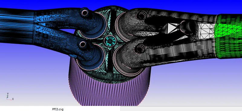
full geometry
CASE SET UP
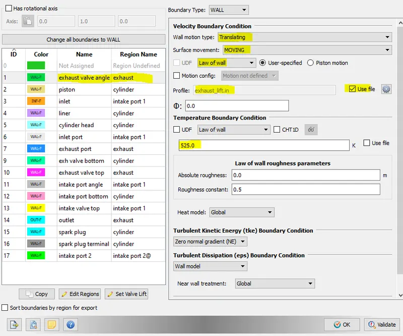
Exhaust valve angle boundary set up
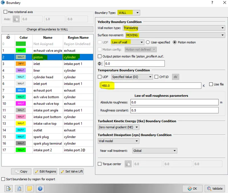
Piston boundary set up
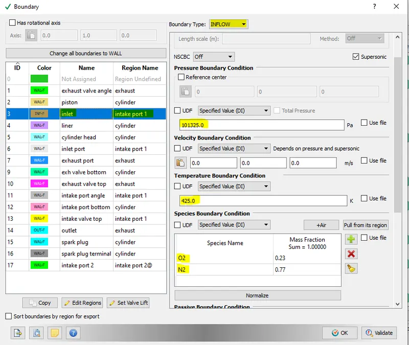
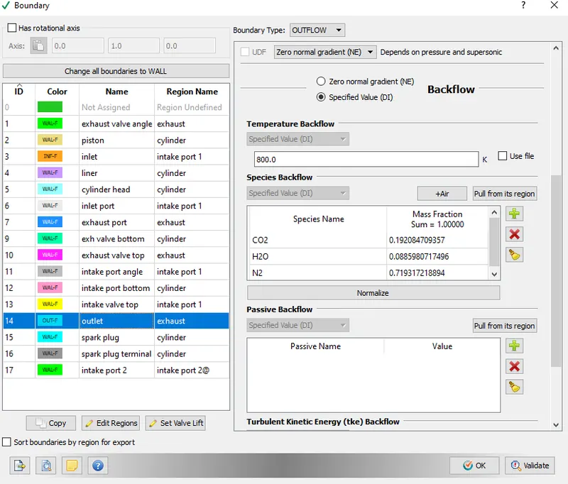
Temperature of different engine components are as follows:
- Piston Temp. =450 k
- liner temp. = 450k
- Cylinder temp. = 450k
- Spark plug temp. = 550k
- spark plug terminal temp. =600k
- Exhaust port temp. = 500k
- Exhaust outflow temp. = 800k
- Exhaust outflow pressure = 1 Bar
- Exhaust valve top temperature =525k
- Exhaust valve angle temp. = 525k
- Exhaust valve bottom temp. = 525k
- Intake port-1 temp. = 425k
- Intake port-2 tep. = 425k
- Inflow pressure = 1Bar
- Inflow temperature = 363k
- inflow species =air
- Intake valve top,angle and bottom temp. = 480k
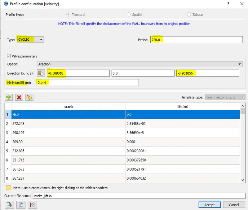
intake valve lift profile
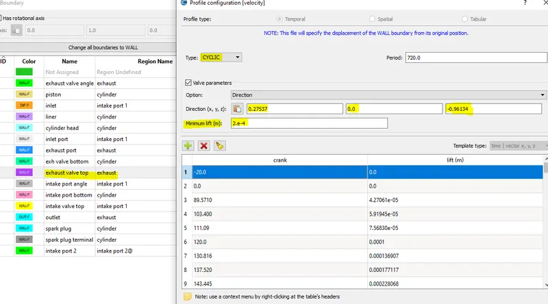
Exhaust Valve lift profile
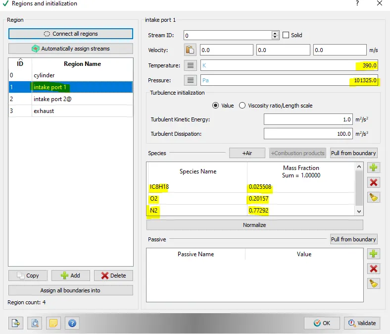
intake port 1 boundary set up
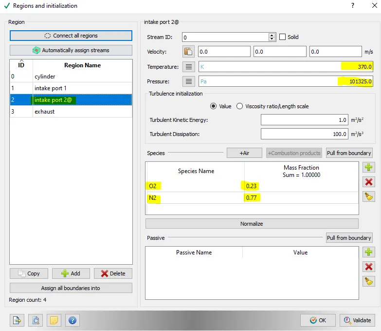
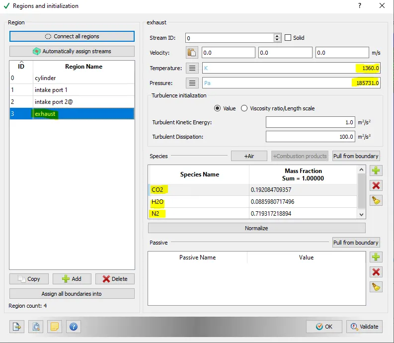
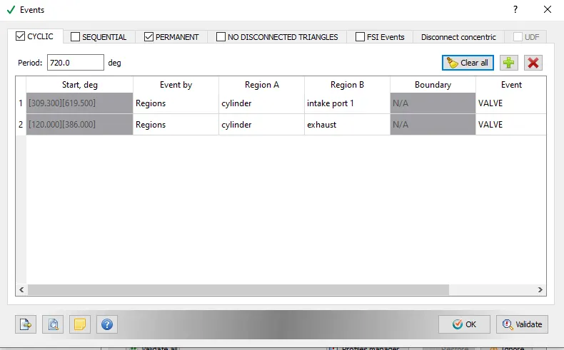
Events set up
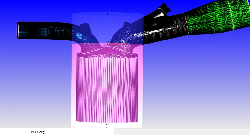
Fixed embedding
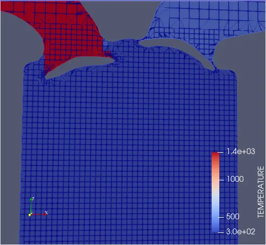
mesh slice at 5 time step
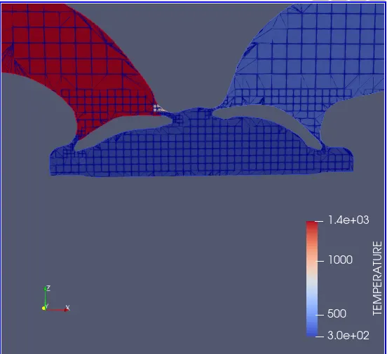
mesh slice at 50 time step
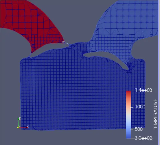
mesh slice at 100 time step
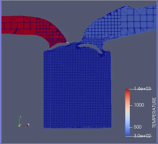
mesh slice at 150 time step
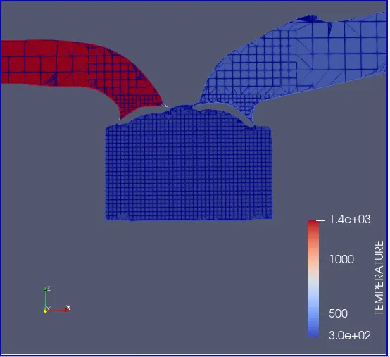
mesh slice at 200 time step
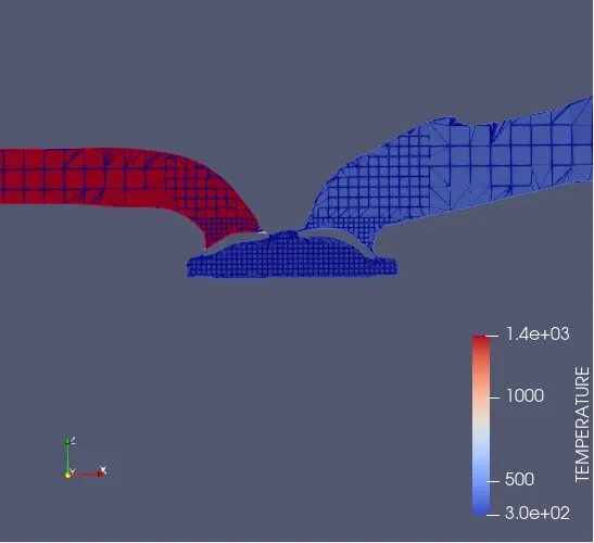
mesh slice at 250 time step
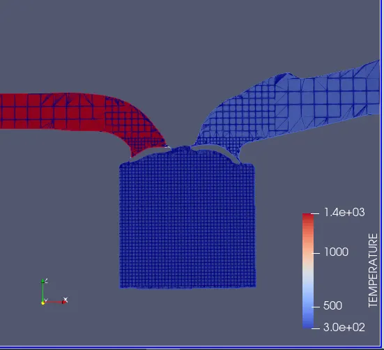
mesh slice at 300 time step
animation no hydro case simulation