Week 9: Project 1 - Surface preparation and Boundary Flagging (PFI)
Aim: To perform no-hydro simulation of an Internal Combustion Engine of Port Fuel Injection type model.
Introduction: In this project, I have used geometry provided by the institution.
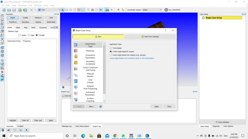
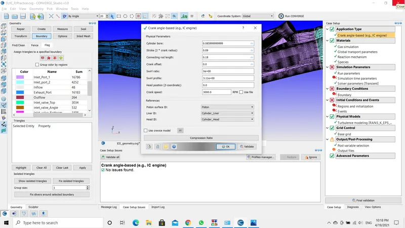
- Firstly, begin the case setup using crank angle-based IC_Engine (Converge V3.0),
- Secondly, flag the boundaries. In this case, as were are solving an internal combustion engine the boundaries are more.
- After completing the required actions export the files and start the simulation using MPI setup.
Theory:
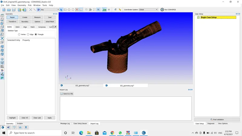
Geometry: Import the provided geometry (.stl file) and begin the case setup(crank angle-based IC_Engine).
--------------------------------------------------------------------------------------------------------------------------------------------------------------------------------------------------------------------------------------------
MATERIALS:
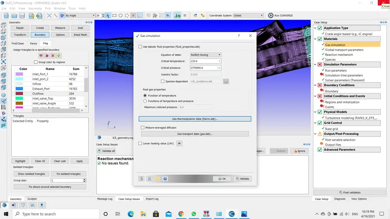
Gas Simulation: Import the therm.dat file in the gas simulation to define the thermal properties of the chemicals.
Global Transport Properties: Accept the default values for this option.
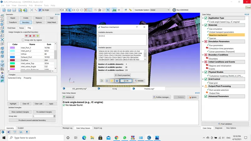
Reaction Mechanism: In this import the mech.dat file. Previously imported file and this file is interrelated.
After uploading the file, click on the check properties to check the errors.
--------------------------------------------------------------------------------------------------------------------------------------------------------------------------------------------------------------------------------------------
SIMULATION PARAMETERS:
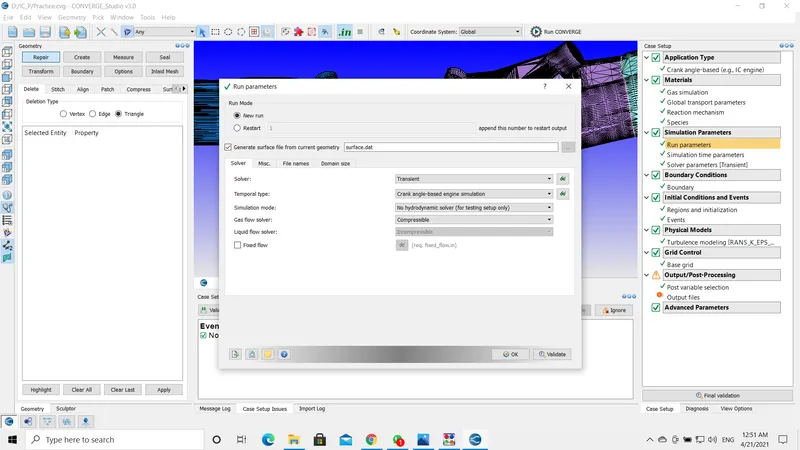
Run Parameters: I am using the No-Hyro Solver method for this simulation.
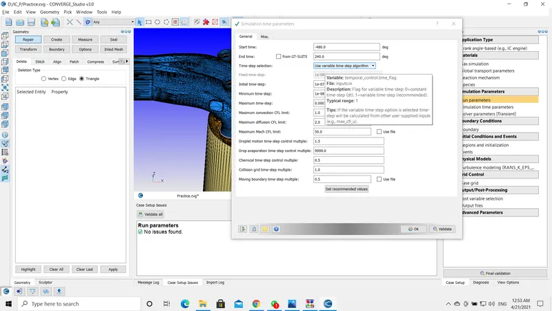
Simulation Time Parameters:
Solver Parameters: I have used the default values.
--------------------------------------------------------------------------------------------------------------------------------------------------------------------------------------------------------------------------------------------
Boundary Flagging:
- Boundaries in this type of geometries are complex to flag. I have also used boundary fencing to divide certain regions.
- initially, when I diagnosed the setup I found many errors, and those errors are solved one by one after flagging the boundaries.
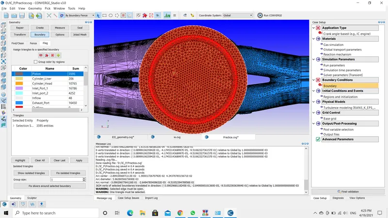
First flag the piston. ie., the bottom surface.
Next, the cylinder liner.
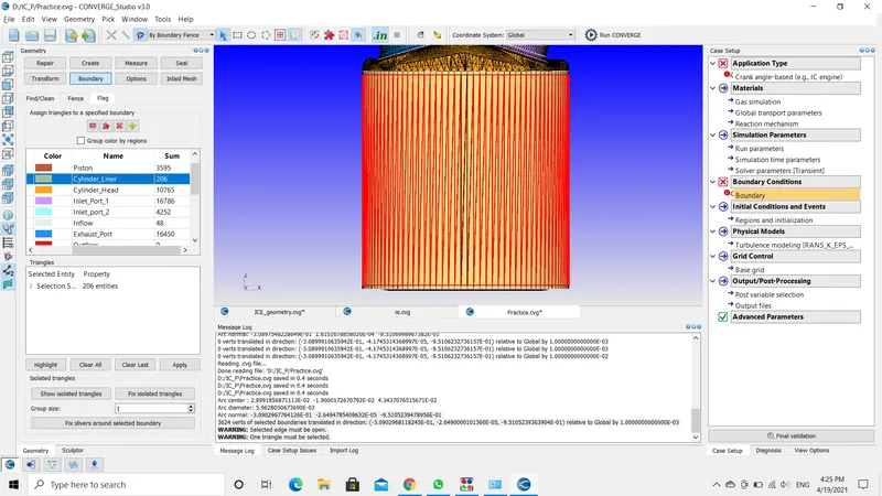
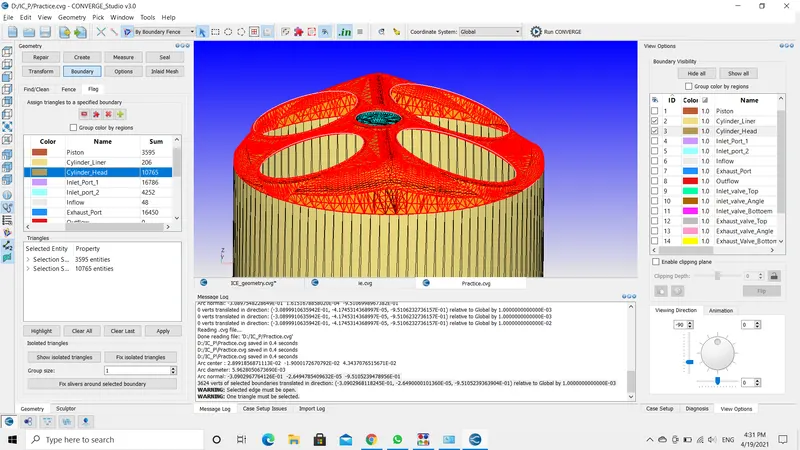
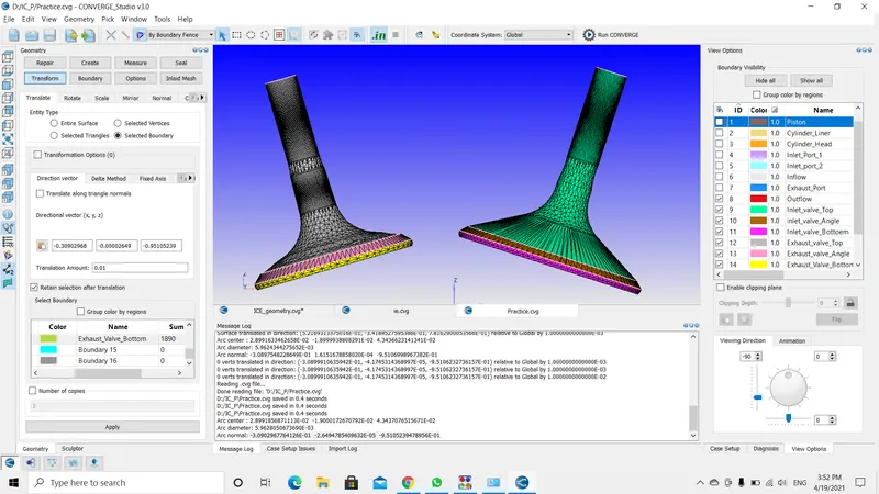
Next, cylinder head. There is some difficulty in flagging the cylinder as the inlet valves are intersecting the inlet port. This problem has been resolved by translating or moving the valves a little bit.
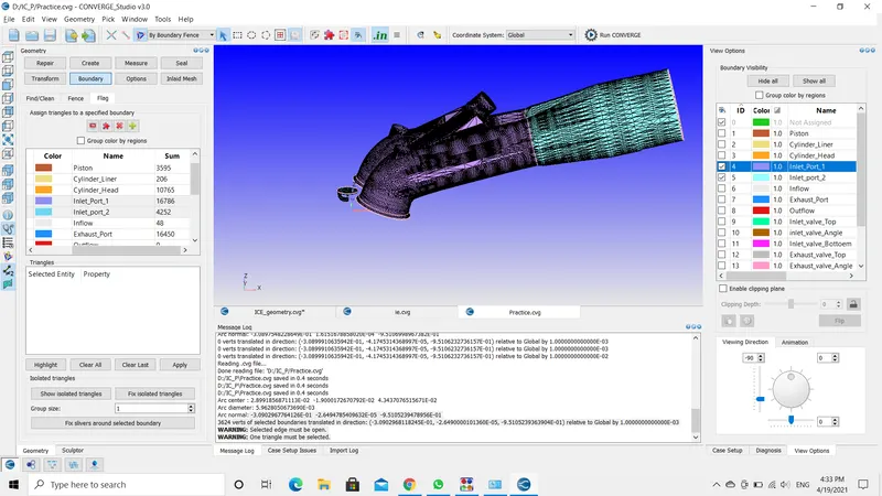
Next, the intake port. Here the intake port has been divided into two parts intake port 1 and intake port 2. This division has been done using the boundary fencing option.
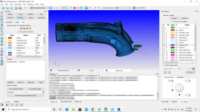
Now the exhaust port. The exhaust port is not divided as the intake port.
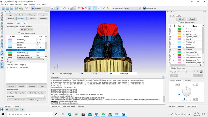
The inflow and outflow boundaries
INFLOW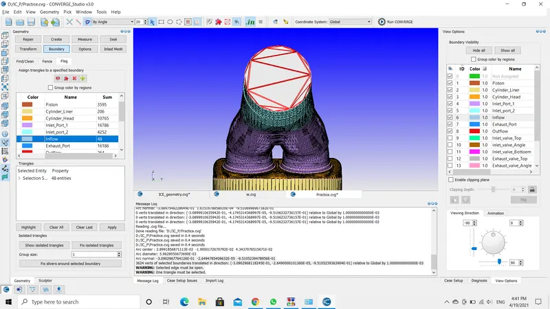
OUTFLOW
Coming to inlet and exhaust valves. These valves are divided into three parts namely valve top, valve angle, and valve bottom as shown below.
Lastly the sparkplug. The sparkplug tip separately flagged and sparkplug terminal. This is because due to the temperature difference. The tip has the greater temperature.
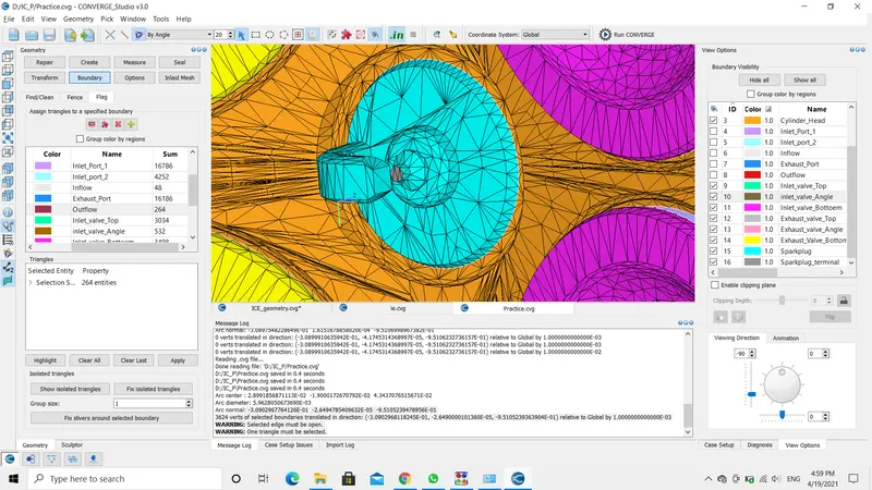
With this, I have completed flagging the boundaries.
Assigning regions to boundaries:
- The below image shows the boundaries with assigned regions.
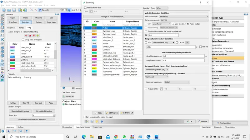
- For the value, I have used the given data, and for the intake and exhaust valves moment include or import the provided files.
--------------------------------------------------------------------------------------------------------------------------------------------------------------------------------------------------------------------------------------------
Initialize Conditions and Events:
In this, add four new regions namely Cylinder_Region, Intake_port_1, Intake_port_2, exhaust_port.
This is done because, in an engine the temperature, pressure, and chemical characteristics not the same in all locations. So, to describe the characteristics and mass fractions four different regions are introduced.
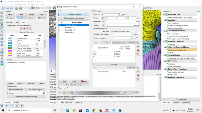
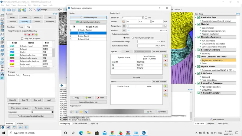
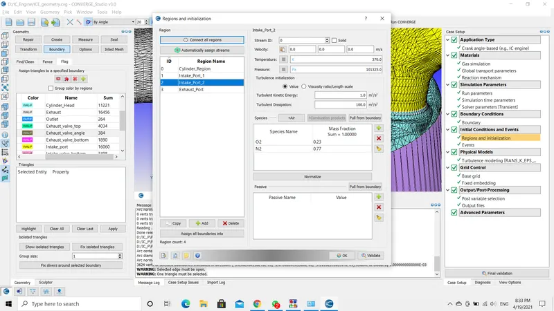
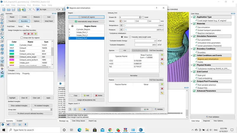
The above pictures display the values of the regions.
EVENTS:
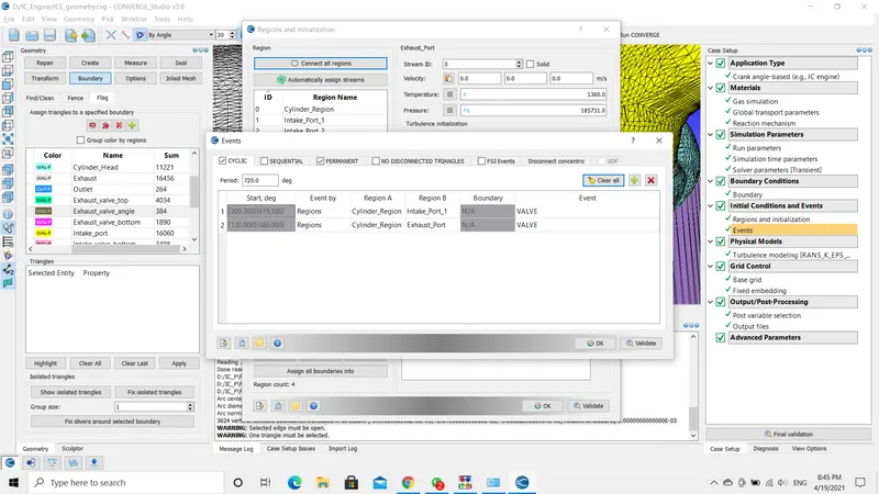
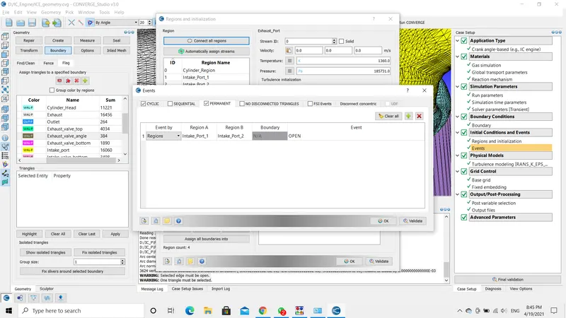
Events are used to allow the fluid flow(air-fuel mixture) between two boundaries or regions. The flow can be done in sequential order or in permanent type.
In sequential type, it allows the fluid flow in the specified period and restricts the flow in other time intervals.
Whereas in our condition, we are using crank angle-based. This data is driven from the boundary conditions.
As I have divided the intake port into two boundaries intake port 1 and intake port 2. I have implemented a permanent opening event here.
--------------------------------------------------------------------------------------------------------------------------------------------------------------------------------------------------------------------------------------------
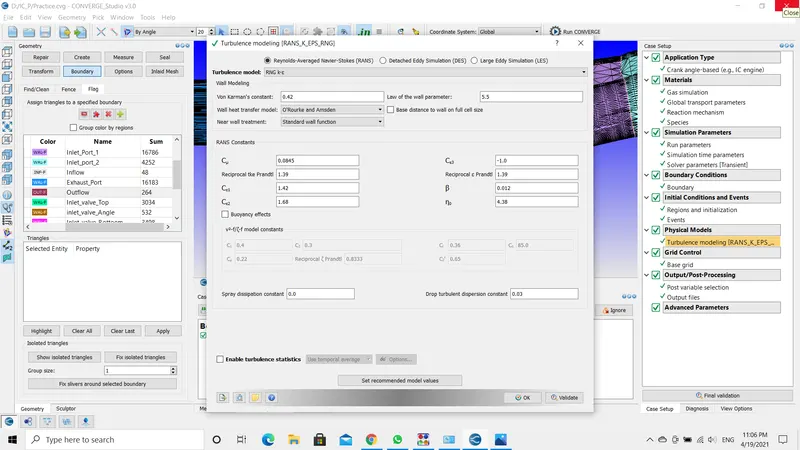
TURBULENCE MODEL: In this use the K-Epsilon with default values.
--------------------------------------------------------------------------------------------------------------------------------------------------------------------------------------------------------------------------------------------
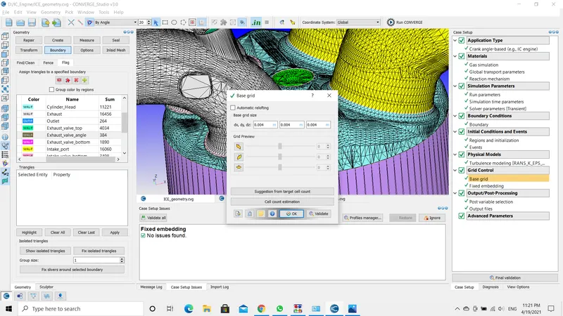
GRID CONTROL: The mesh size is 0.004 meters.
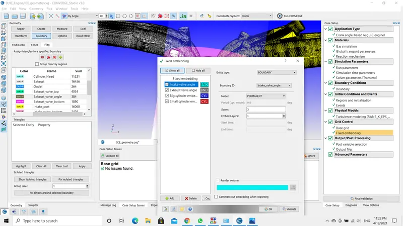
- Include the fixed embedding in four places, at inlet and exhaust valve angles, other two along with the cylinder liner.
--------------------------------------------------------------------------------------------------------------------------------------------------------------------------------------------------------------------------------------------
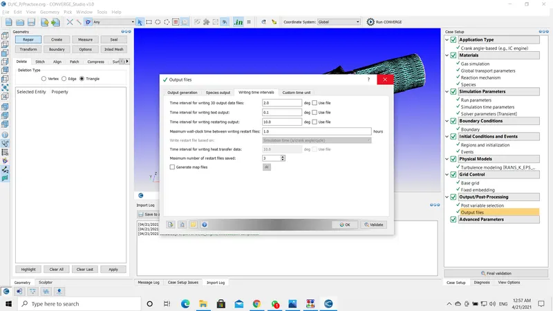
OUTPUT: To generate the 3D output files I have used the following valve.
--------------------------------------------------------------------------------------------------------------------------------------------------------------------------------------------------------------------------------------------
RESULTS:
--------------------------------------------------------------------------------------------------------------------------------------------------------------------------------------------------------------------------------------------
CONCLUSION:
- I have used the crank angle-based case setup in this simulation.
- It takes 720 degrees to complete one cycle or four strokes.
- The simulation time starts at -480 degrees and ends at 240 degrees.
- For material properties, I have used the mech.dat and therm.dat file provided here in the challenges, these have all the necessary properties have the thermochemical properties required for the simulation to be conducted.
- Next, for simulation parameters, I have used the values provided on the challenge page.
- It is important to be cautious while flagging the boundaries. I have used the boundary fence method to differentiate the parts, in certain areas it would be hard to complete the fencing process. It is advised to fence carefully.
- The reason behind flagging three boundaries for inlet or exhaust valves is, firstly, the valves are located in two regions, in inlet port 1 and also in cylinder head the temperature in the cylinder region and inlet port are not the same.
- And in the simulation, the valves are not completely closed there is some gap between the valve angle and cylinder head due to this there might be a flow of fluid. So, to restrict the flow Converge creates a ring around the valve angle that stops the flow when the fuel is not needed in the cylinder.
- The boundary set up is incomplete until each boundary is assigned to a particular region. Simulations like IC_Engines have more regions, in order to describe the thermophysical properties.
- I have uploaded the regions setup images above for reference.
- Another important aspect is to import the valve profile (inlet and exhaust valve). This file guides the valve opening and closing at each and every crank angle.
- After completing the setup and simulation, I was able to generate 360 post files and the results uploaded above.
- The results show the opening and closing of valves accurately and expected crank angle moments are seen.
- For this simulation, I have used the No-Hydro solver because we are focusing only on the movement of the valves and piston. The No-Hydro solver just generates the mesh.