Week 9 - Project_1 - Door Trim Lower with Engineering Features
DOOR TRIM LOWER WITH ENGINEERING FEATURES
OBEJECTIVE:
To Create the Door trim lower plastic Component with the B-side Engineering features from the given ref points with respect to the Class-A surface.To Create the appropriate tooling axis for the given Class-A Surface & Attachments meeting the requirements of the draft angle.To Attach B side Features in the component. And also to perform the Draft analysis on the model.
GIVEN:
Thus the following as the Input of this components Class-A Surface with the ref points.
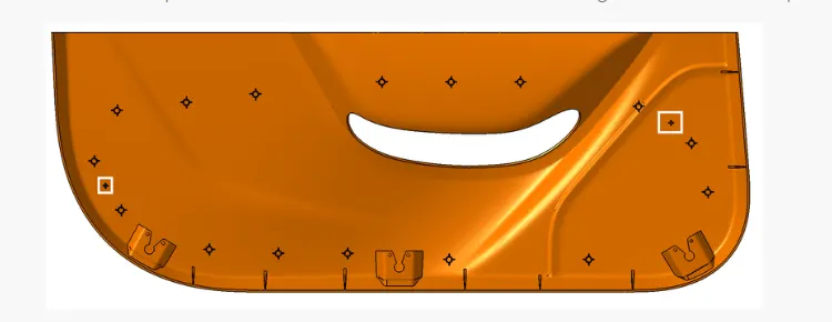
From the above ref pic. we founf the B-side Engineering features of Heatstakes & Locators is there and here let us consider the following,
For Heat Stakes,
Consider Heat Stakes Boss dia (OD) = 8 mm.
For Locators,
Thicknesss = 1.3 mm.
Thickness of the Plastic Component is = 2.5 mm.
TOOL USED: CATIA V5
STAGE_1: TOOLING AXIS CREATION
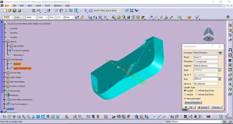
The Tooling Direction which one is the direction that the mold pulls apart. The mold is built in two separate halfes of like Cavity side and the Core side. The Core pulls out from the Cavity along with the certain direction which is called as Tooling direction or Tooling Axis.
- Bisecting Method is one of the Tooling axis Creation method. For this method it should be consider two line getting bisected along with ref point over here obtains in between line(Dummy axis). Then follow the same to define the Main Tooling axis from the Dummy Tooling axis.
From this given Class-A surface, here I prefer to go with Point to Direction Method for creating Main tooling axis. And the following as,
STAGE_2: DRAFT ANALYSIS FOR CLASS-A
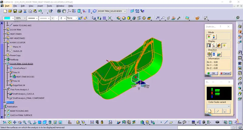
By using of Feature Draft Analysis with the Minimum draft angle of 3 deg along with the above Main tooling axis. Thus the results shown here as following as,
STAGE_3: SURFACE MODELING
STEP_1: CLASS-B SURFACE CREATION
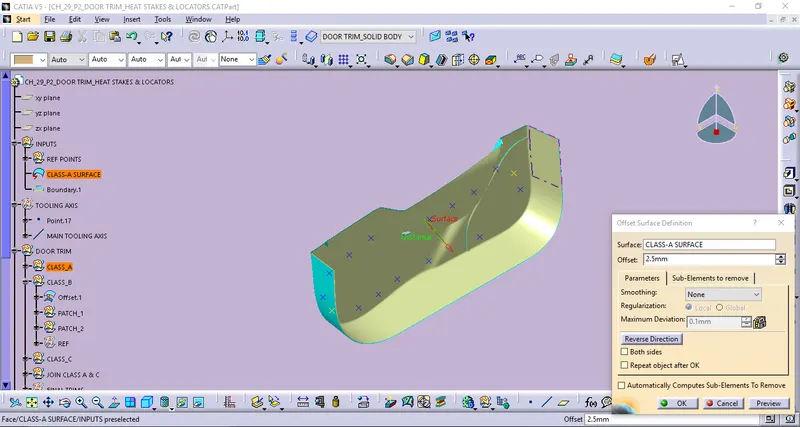
Class-B surface, In which can be easily defined as the thickness of the part and it is not visible which is inside surface of the Class-A. For the following plastic component thickness as 2.5 mm from the Input data. While offseting Class -A for 2.5 mm of thickness directly by applying Offset surface definition And then we B-side of the following one which have some of its patch holes/no surfaces obtained over there. Then the patchs will be created into simplified surfaces to be obtain the complex one which Class-B surace. And the following solvings are,
By using of offset surface definition.
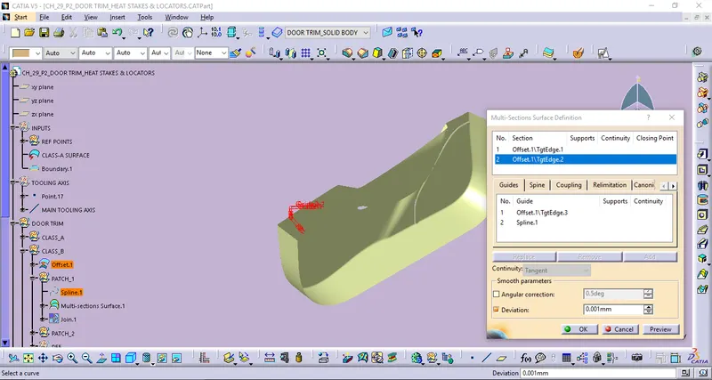
By defining Multi-Section Surface Definition.
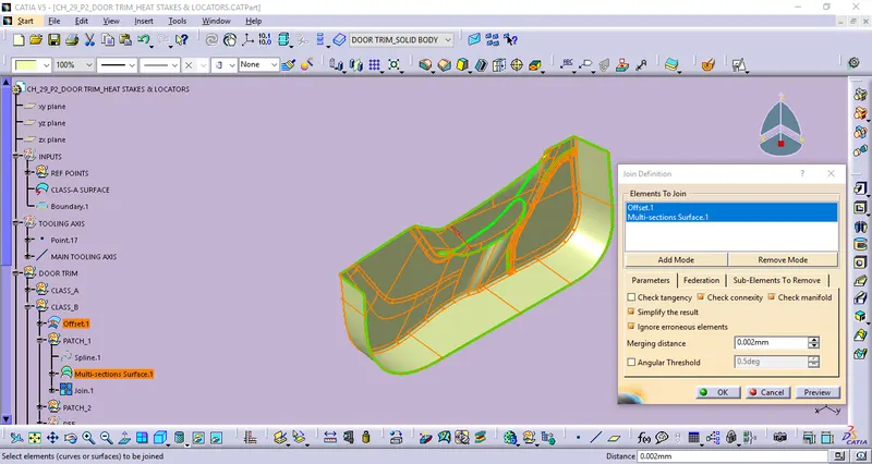
By using of Join definition.
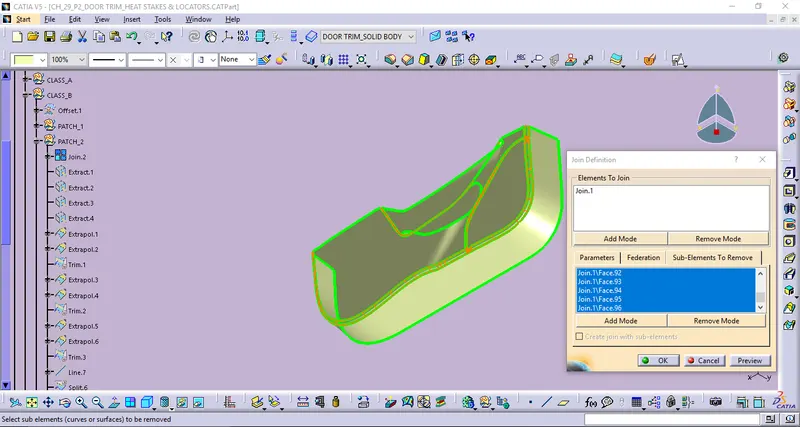
By using of Join- Sub-elements to remove method and following results are,
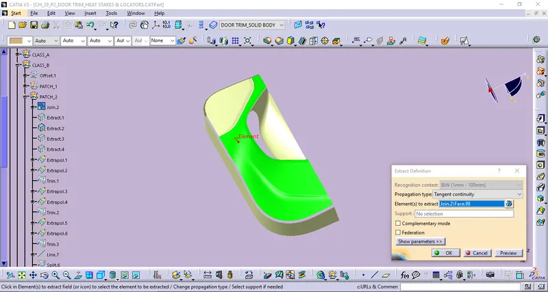
By using of Extract definition.
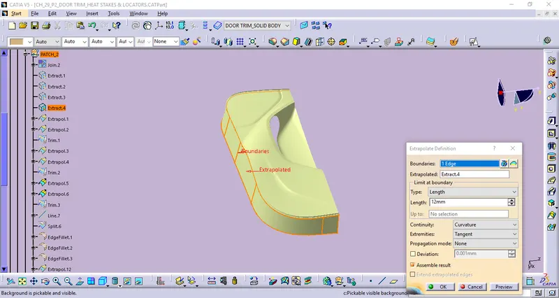
By using of Extrapolate definition.
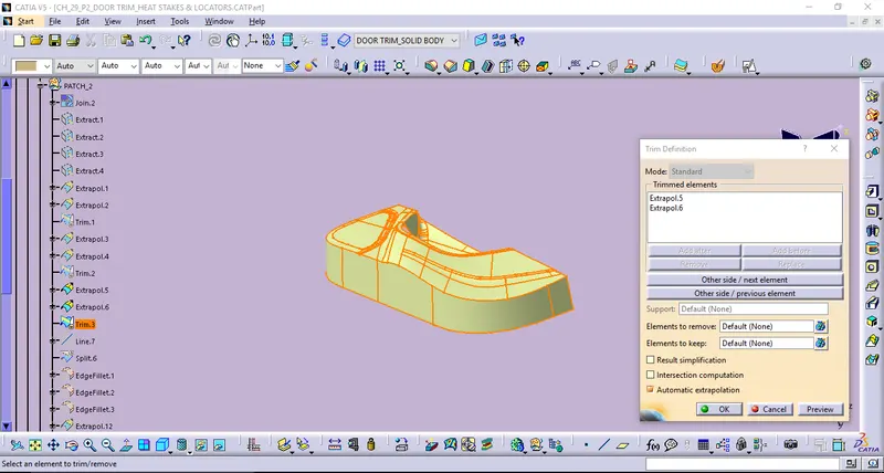
By using of Trim definition.
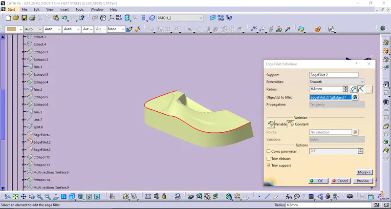
By using of Edge fillet definition.
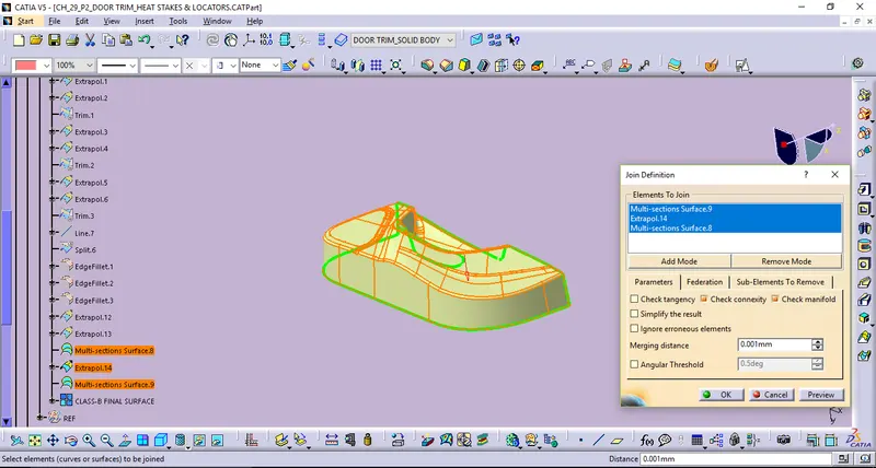
By using of Join definition.
STEP_2: CLASS-C SURFACE CREATION
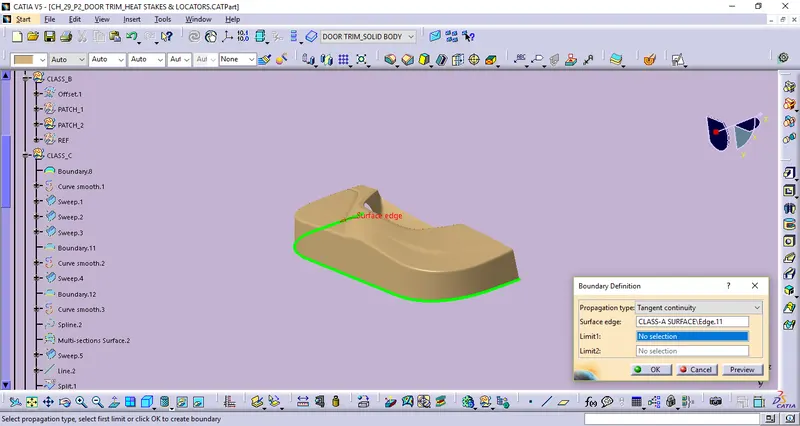
By defining the Class-C surface with respect to the Class-A surface. From the Class -A surface edge boundaries used to performed to create the Class-C surface. And the some of its workings are,
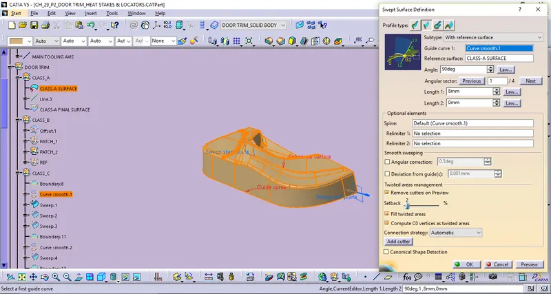
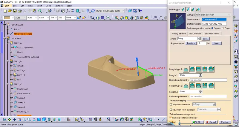
Commands used: Swept surface(type-2) with drfat direction , Swept surface(type-2) with ref surface, Boundary, Curve smooth, Extrapolate, & Trim.
By using of boundary definition.
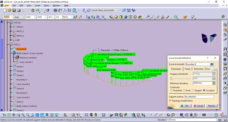
By using of Curve Smooth definition.
By defining of Swept surface definition with ref.surface.
By defining of Swept surface definition with draft direction(draft angle of 3deg) along with the Main tooling axis.
By using of Extrapolate definition.
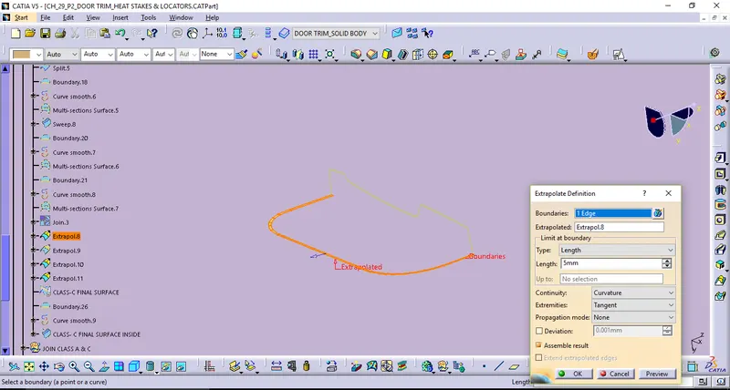
By using of Trim definition.
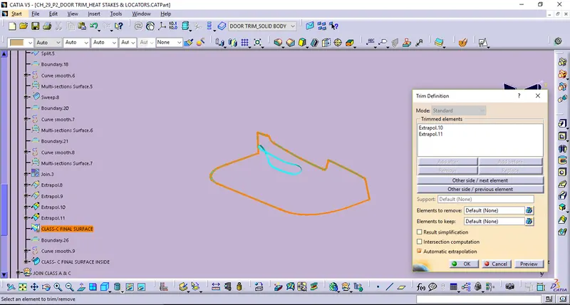
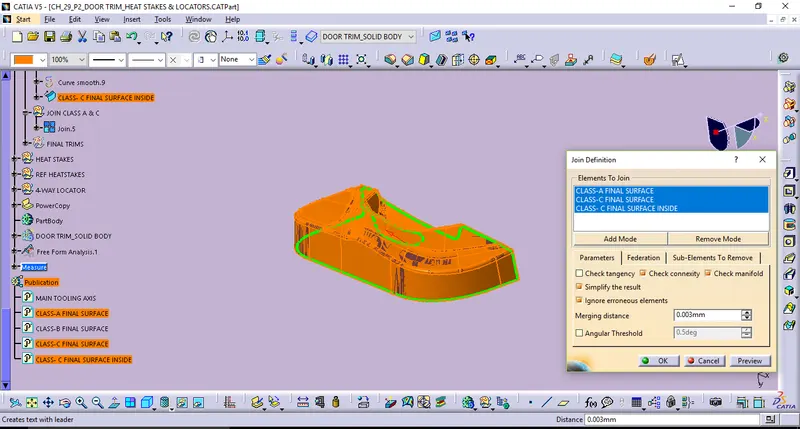
STEP_3: JOIN CLASS-A & C
By using of Join Definition.
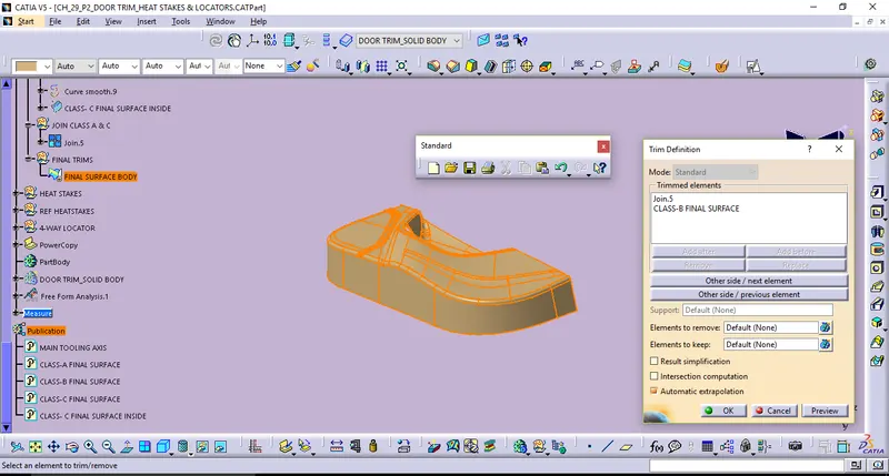
STEP_4: FINAL TRIMS
By using of Trim Definition.
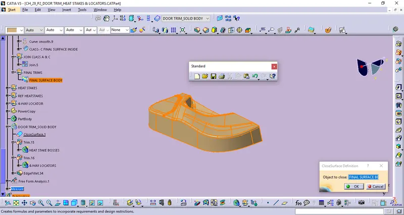
STAGE_4: SOLID PART_CLOSE SURFACE
By using of Close surface Definition.
STAGE_5: ATTACHMENT FEATURE CREATION & ITS DRAFT ANALYSIS
HEAT STAKEBOSS CREATION
Heat staking also known as thermoplastic staking is the process of joining two dissimilar materials together. In heat staking we use local heating and cooling to raise the temperature of plastic components and allow plastic reforming to be carried out. And the Heat stakeboss creation procedure as following solvings,
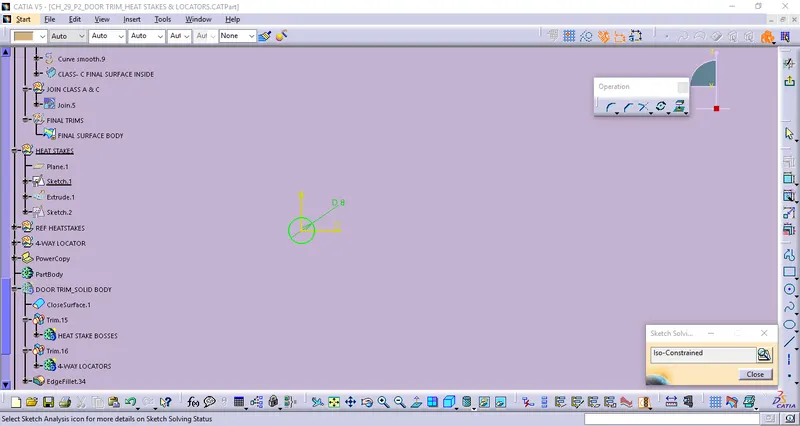
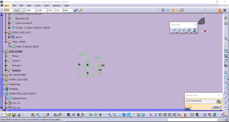
Thus the following Sketch becomes Positioned Sketch also Iso-Constrained.
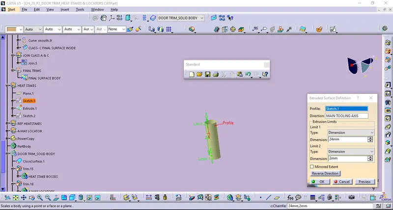
By using of Extrude Surface definition along with the Main tooling Direction.
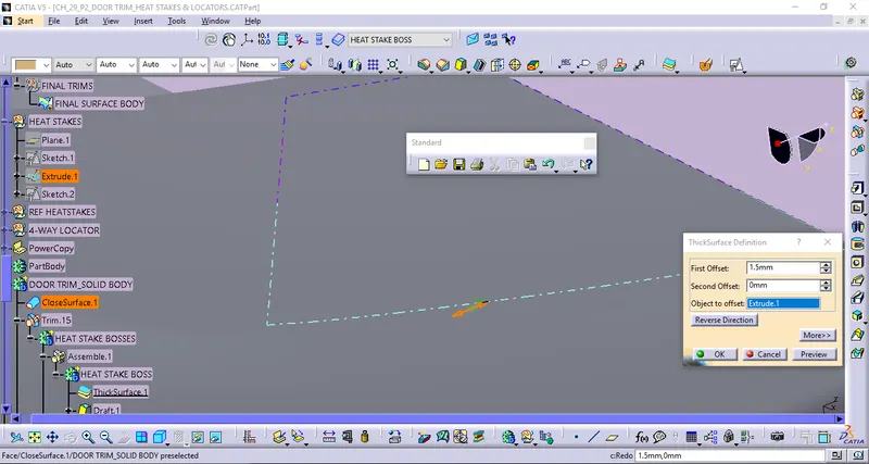
By using of ThickSurface definition.
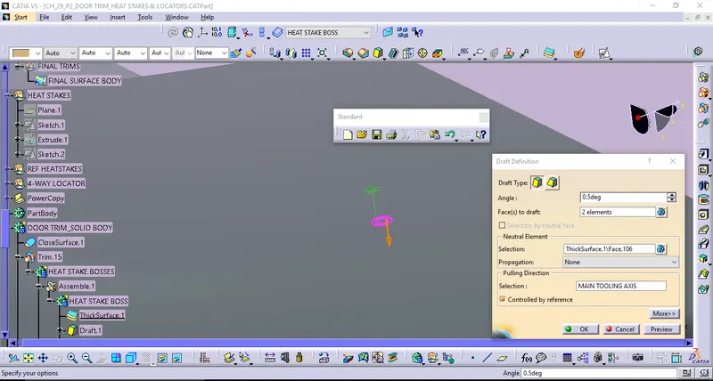
By defining draft 0.5 deg along with the main tooling axis.
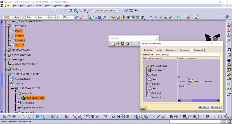
By using of Power Copy definition method we could define remains get copies by using the ref points.
LOCATORS - 4-WAY LOCATOR CREATION
Locating Devices describes the components used to position a workpiece in a workholding device. Locating is a crucial part of effective workholding. Locators come in a wide range of available types with various features. To perform properly, workholders must accurately and consistently position the workpiece relative to the cutting tool, part after part. To accomplish this, the locators must ensure that the workpiece is properly referenced and the process is repeatable. And the followings are Locator solving of 4-way locator,
Thus the following Sketch becomes Positioned Sketch also Iso-Constrained.
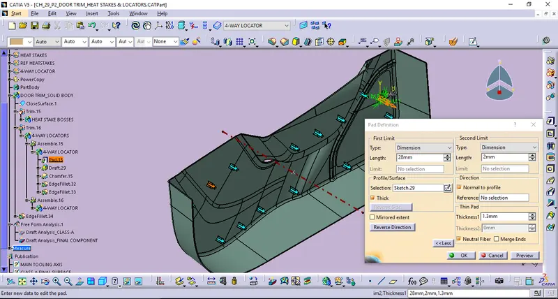
By using of Pad definition.
By using of Draft with 0.5 deg alog with the main tooling direction Definition. Then it will gets copied and Paste special as link with results then placed thus the same into another position.
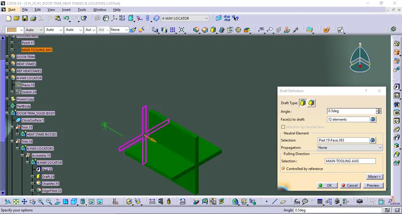
STAGE_6: OBTAIN FINAL COMPONENT_BOOLEAN OPERATIONS
By using of Union Trim.
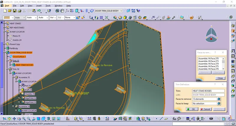
By using of Union Trim.
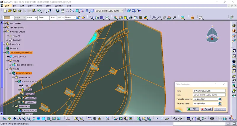
By using of Edge Fillet Definition.
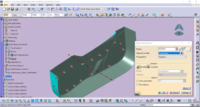
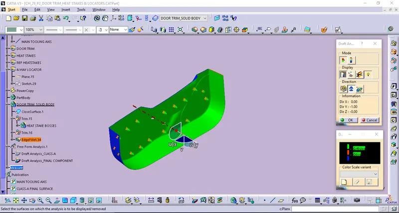
STAGE_7: DRAFT ANALYSIS FOR FINAL COMPONENT
Draft analysis for the final component along wint the main tooling axis wint the draft angle of 0.48 deg.
VIEW ORIENTATIONS:
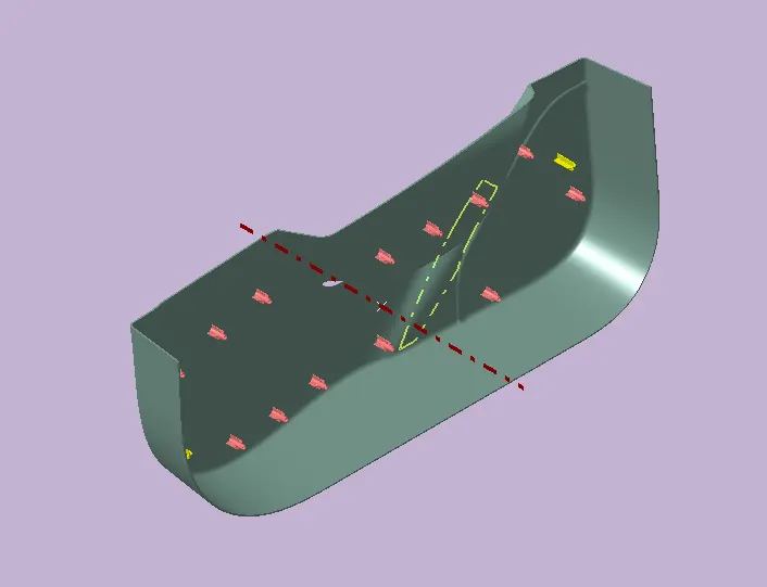
ISO VIEW
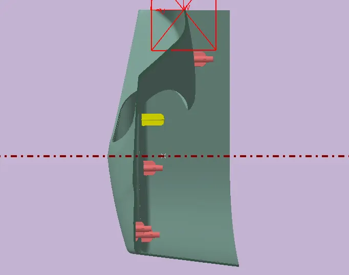
SIDE VIEW
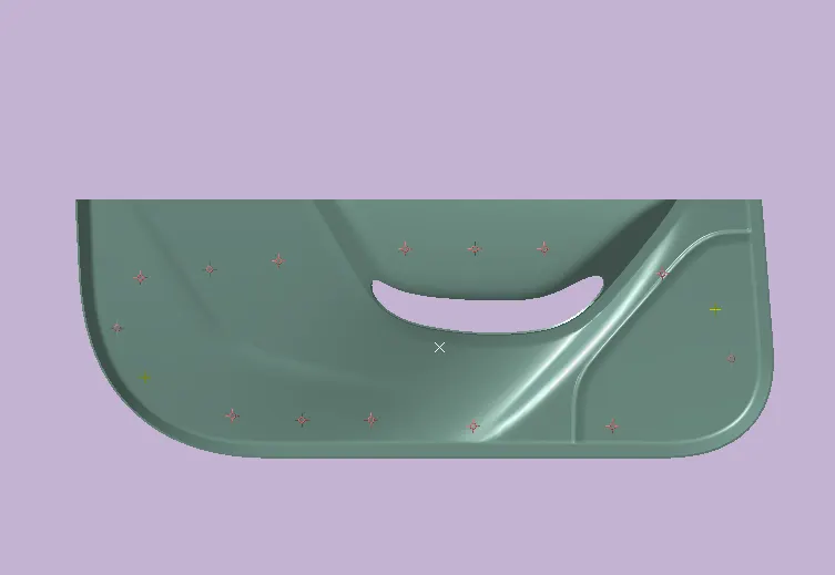
SECTION VIEW
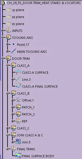
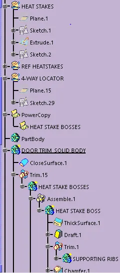
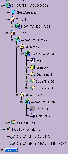
TREE STRUCTURE:
CONCLUSION:
Thus the Door trim lower plastic Component with the B-side Engineering features design sucessfully created by using CATIA v5.
And the followings also,
Tooling axis for the given Class-A Surface and its Draft analysis to be completed.
B side Attachment Features in the component & its Draft analysis for both the Dog House along with Side Core Axis and the Final component completed.