Week 9 - Project_1 - Door Trim Lower with Engineering Features
DESIGN OF THE DOOR TRIM LOWER WITH ENGINEERING FEATURES INCLUS HEAT STAKES,LOCATORS & RIBS
Aim: To design the door trim lower component from the given class A surface and create the engineering features ( heat stakes and locators ) on the component using CATIA V5 software
Objectives:
Creation of Tooling axis with appropriate draft angle.Creation of other surfaces (eg, B and C surfaces) for creating a solid component. • Perform Draft analysis on Class A surface and Solid model hence created.
Procedure followed:
The following steps are included while designing the door handle with B side features
- Tooling axis creation
- Draft analysis of class A surface
- Class B surface generation
- class C surface generation
- Final trim
- Solid body generation
- Draft analysis of the solid body
- Locator creation
- Heat stake creation
- Translation
- Draft analysis of the B side features
Class A surface:
Class a surface is an asthetic surface with a polished surface which will be visible for the customers, and with the aid of the class A we could be able top geneate the class B and class C surfaces
Class B surface:
class B is an engineering surface where the B side features include the ribs, screw bosses , doghouses are located
Class C surface:
Class c is an intermediate surface between the class A and class B surfaces.It is generated by sweep feature either with reference surface or with the draft direction.If the generated C surface is parallel yo the tooling axis then we make the aid of the draft direction or else proceed with the reference surface
Commands deployed:
Surface commands:
- Extract
- Boundary
- Extrapolate
- Sweep
- Join
- Trim
- Intersect
- Multi section surface
- Surface extrude
- Multi extract
Part Workbench commands:
- solid surface
- Thicken
- Pad
- Draft
- Fillet
Tooling axis creation:
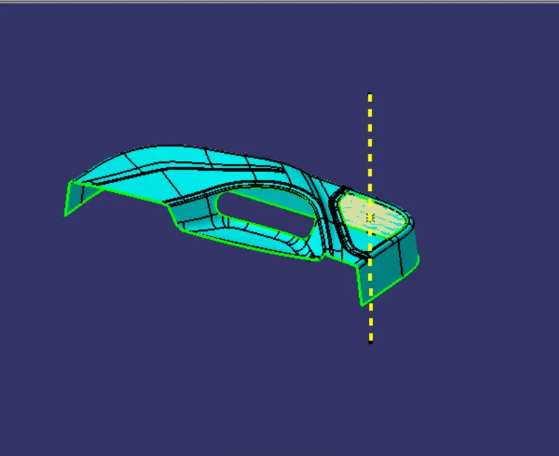
Orient the class a surface in various views and opt the best view to manufacture the part in a single go. Then extract the surface out from the class A surface and create a point at the mid point of the extracted surface and create a line in the view direction. and mark it as the tooling axis
Draft analysis on class A surface:
Now perform the draft analysis of the Class A surface with respect to the tooling axis created so that the surface of the Class A need to clear the draft of 3mm
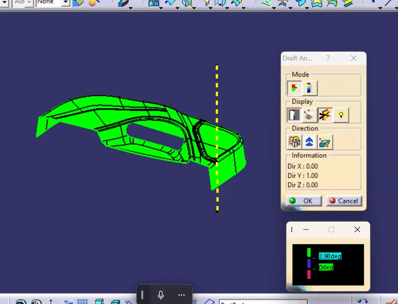
So the class A surface is perfectly claering the draft analysis so we need to move further for the creation of the class B surface
Class B surface creation:
Now offset the class a surface to a thickness value of 2.5mm so there in the offsetted surface we encounter some patches, so we need to work on them to create the Class b surface
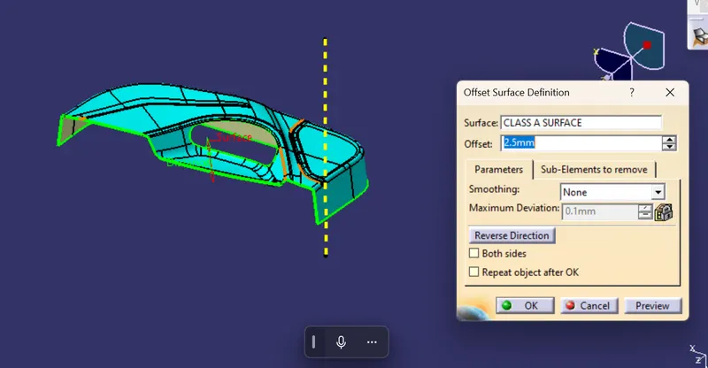
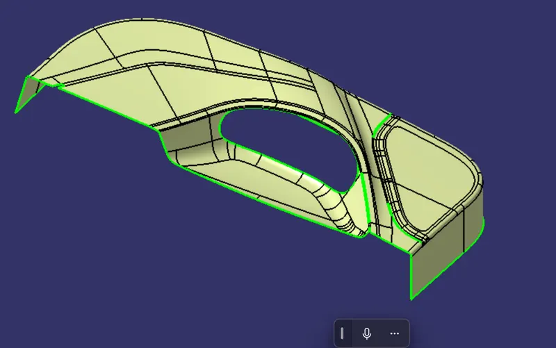
For working on these patrches I divided the class A surface into 4individual patches excluding the fillets as the fillets would create miore problem so we need to apply them at the end and extrapolate them to a sufficient length
so , thet proper interaction should be formed between the patches.
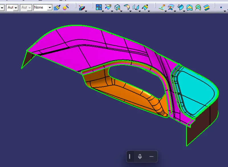
Now apply the trim to form a combined surface and apply the fillet value to obtain the required class B surface
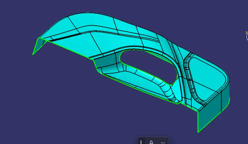
Class C surface creation:
Genearlly class c surface is the surface that lies as an intermediate joining between class A and class B surface Generally class C is grnerated by using class A surface.For this the class A is subdivided into two surfaes oneis the entire body and other one is the patch at the holder So rather then sweeping the entire surface better to do it by surface to surface so that there might be no problem at the final trim or final joining operation
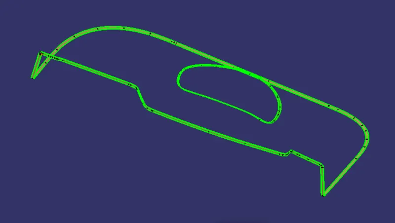
Now join class A and class C surfaces
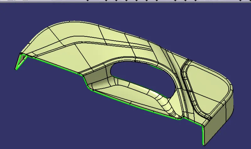
Now trim the class B surfcae with the combined class A and class B surface to obtain the final plastic component
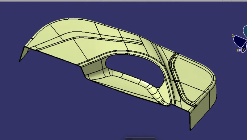
Now do the draft analysis for the component check wherther it is claering all the surfaces draft or not then proceed or else make the surface modification to clear the problem
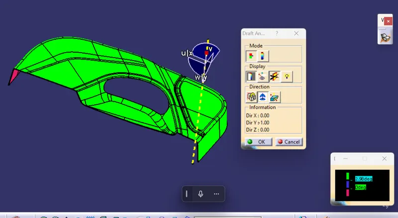
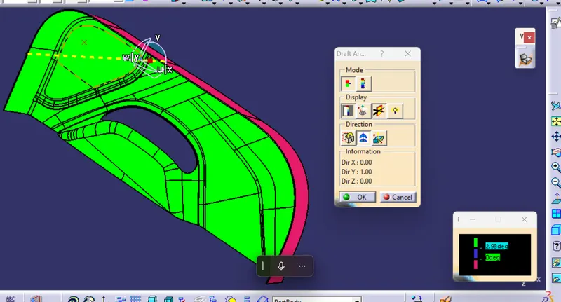
some surfaces on the class c cant be able to clear the draft because due to the class A surface Some modifiction need to be done on the class A to obtain better draft analysis on the complete body
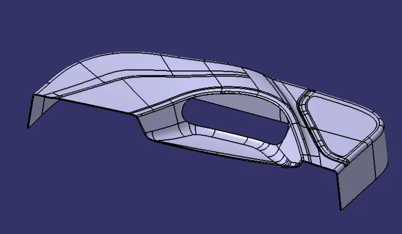
After completing the draft analysis ues the solid surface feature to generate a solid body
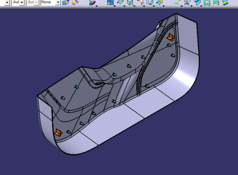
ISOMETRIC VIEW
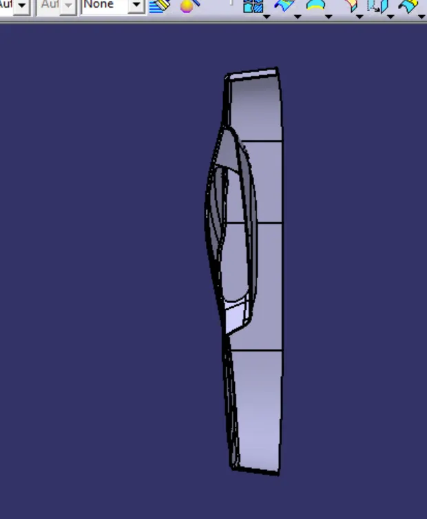
SIDE VIEW
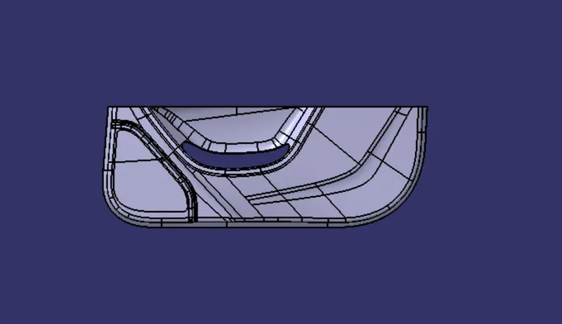
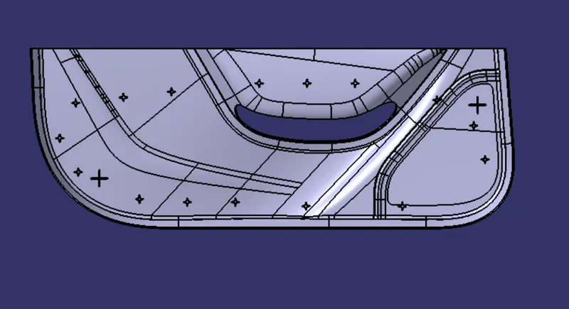
TOP VIEW
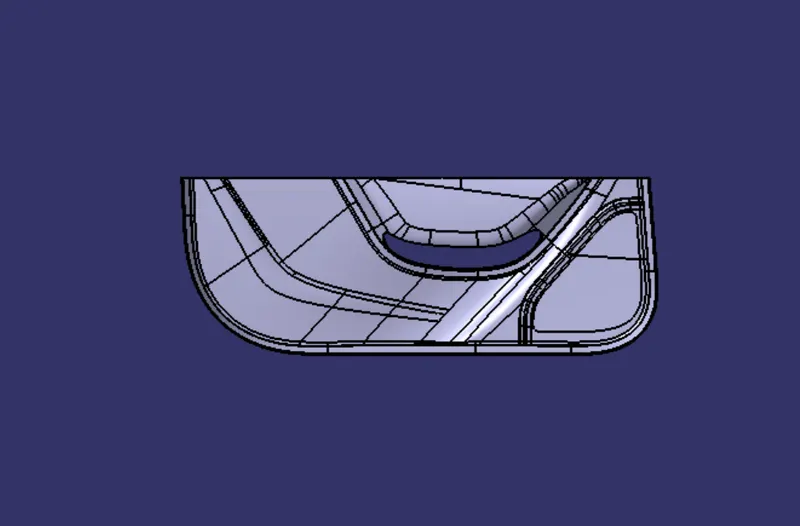
BOTTOM VIEW
Creation of B side features:
CREATION OF LOCATORS:
To create the locators, I created a sketch on the body. After creating the sketch, I pad it 22mm in height and thicken it to 1.3mm and I drafted it with 0.5deg in the direction of the tooling axis. I gave 5mm of chamfer with 45deg of inclination and after I gave a fillet of 0.3mm radius.
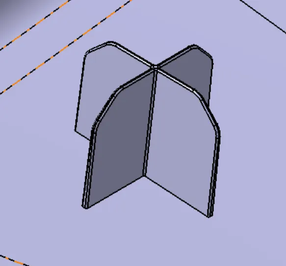
4-way locator:
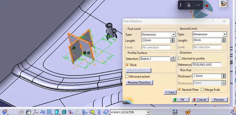
so we need to extend it in the bottom side so we can apply union trim the locator with the main body
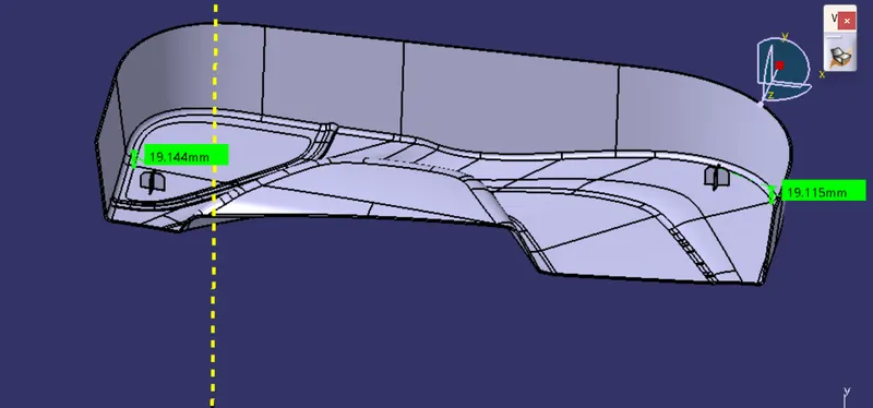
Now use the translate feature to create the another locator
So the distance of the two locators from the surface shoulb be same
CREATION OF HEAT STAKES:
To create the heat stakes, I draw a sketch on the surface. After the creation of the sketch, I pad it to 16mm height and I gave a draft angle of 0.5deg on both sides (inside and outside) and then I gave a fillet with a 0.mm radius. 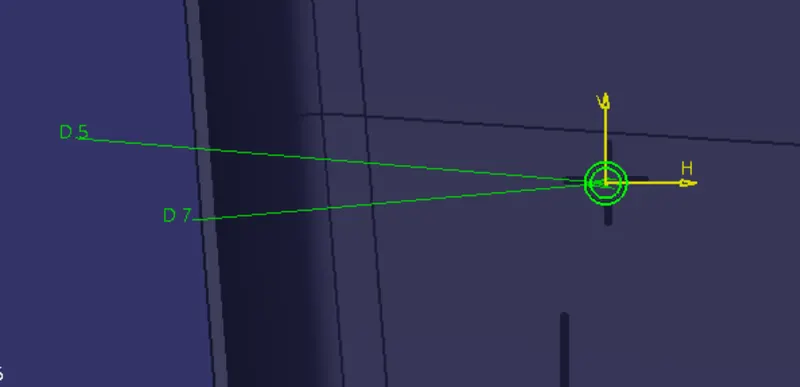
Now pad the heat stake to a height which must be less than the height of the locator nearly 5 mm less than the height of the locator as the locator is the first fastening feature then conmes the heat stakes so ,extend the pad in the bottom side so as to union trim with the main part body
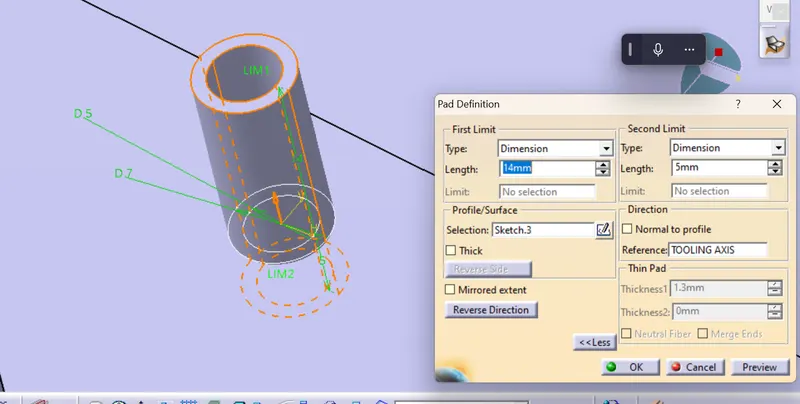
Now apply the draft of 0.5 degrees inide and ouside with the pulling direction as the tooling axis
Now create the Ribs on the 4 sides to support the heat stakes by following the proper rib design parameters and the height of the rib should be 50 % the height if the heat stake abd apply the draft of 0.5 degrees along the tooling axis and apply the chamfer of 3 mm with 45 degrees and apply fillets of 0.25 mm
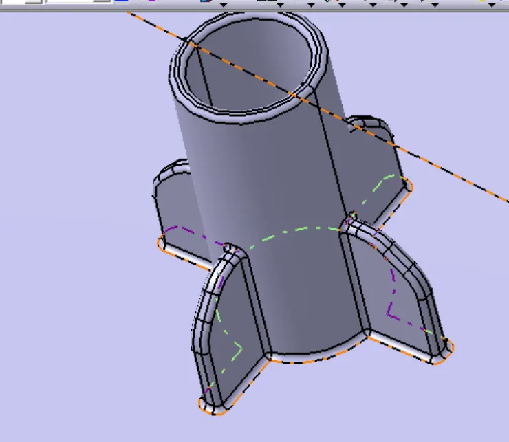
Now we need the generate the heat stakes all around the locator points provided so we need the copy the body of the part created and paste special in the main part component and use the point to point translation to cfeate all the heat stakes
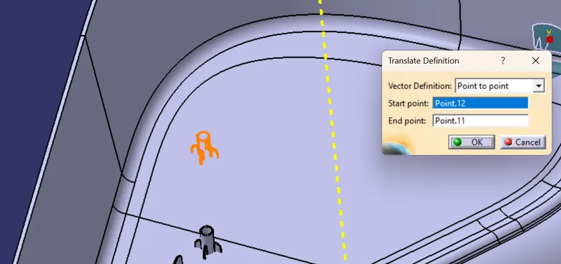
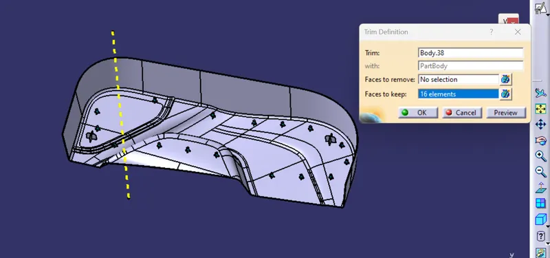
Now assemble all the heat stakes in a single solid body and perform the union trim with the main part body by providing the faces to keep in the union trim feature
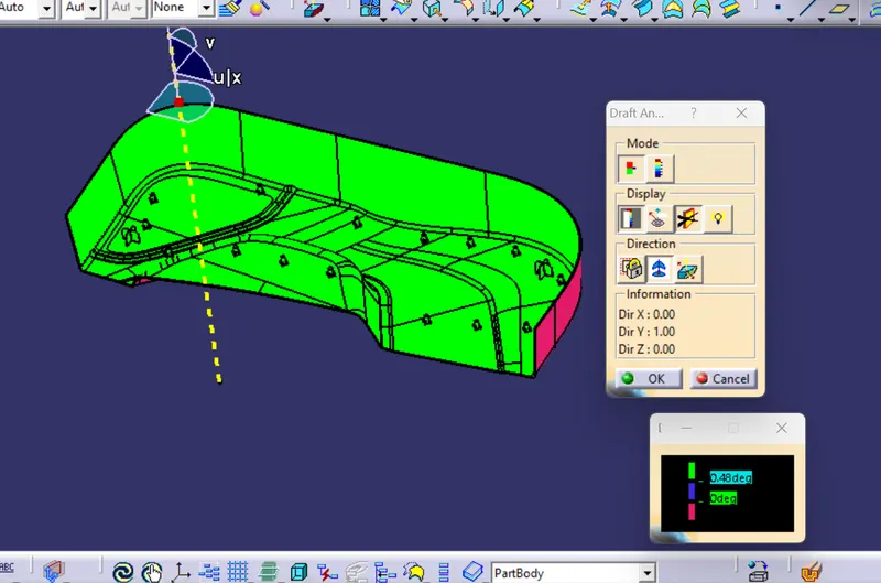
Now perform the draft analysis on the engineering features with a draft angle of 0.5 degrees
Conclusion:
Hence the door trim lower with the engineering fetures including the heat stakes and the locators are designed with the help of the class a surface provided and following the standard design parameters for the B side features using catia v5 software and the cat part is submitted in the browse option
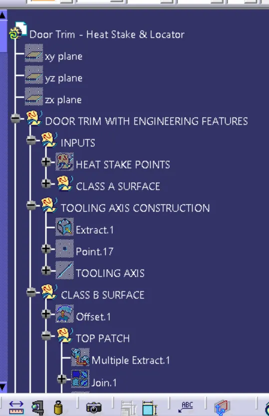
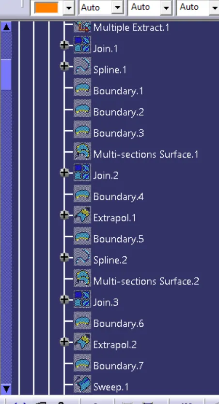
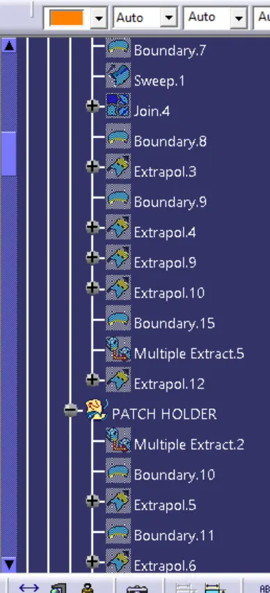
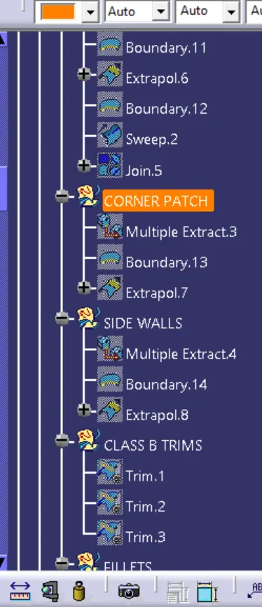
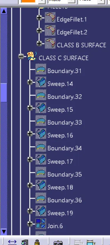
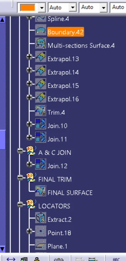
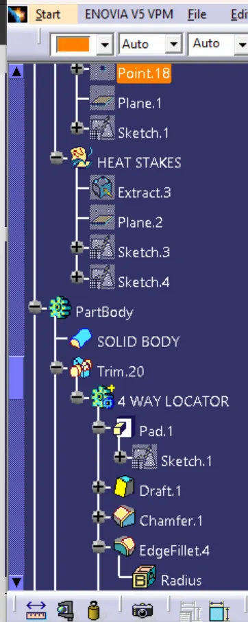
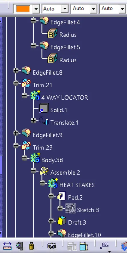
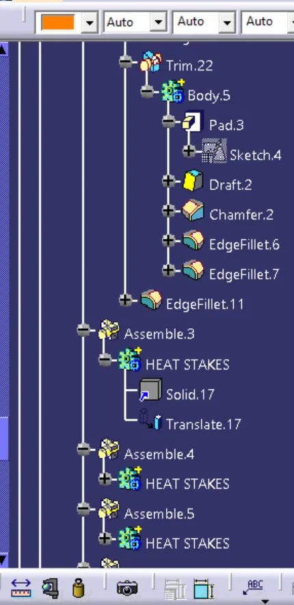
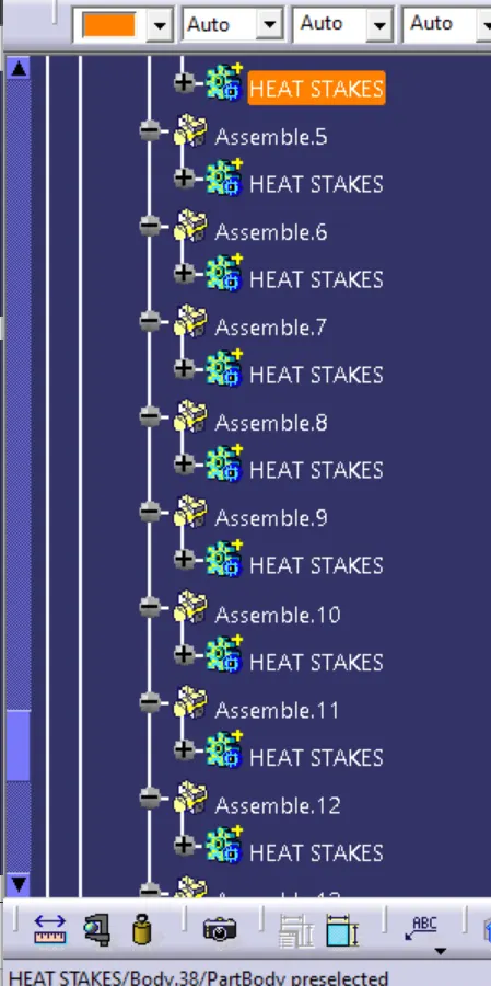
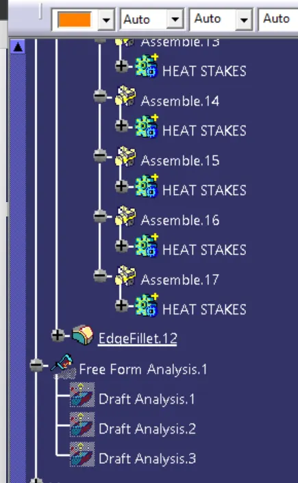
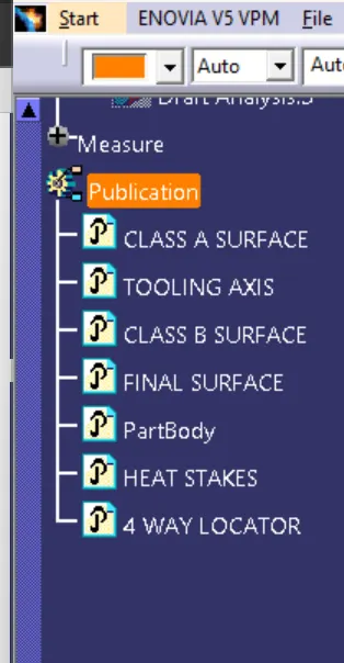
Tree structure
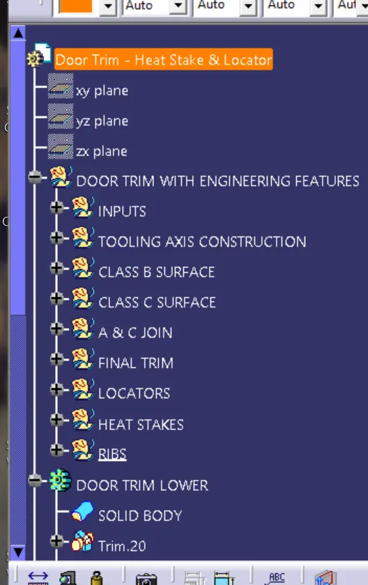
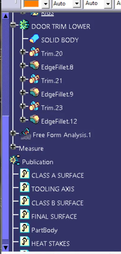
ENLARGED TREE STRUCTURE