Week 9 - Project 1 - Door Trim Lower with Engineering Features
PROJECT 1 - DOOR TRIM LOWER WITH ENHINEERING FEATURES
DESIGN PROCEDURE -
1) Class A surface check.
2) Creating tooling axis.
3) Draft analysis on Class A surface.
4) Creation of Class B surface.
5) Creation of Class C surface.
6) Final trimmed surface.
7) Convert surface to solid.
8) Creation of locators.
9) Creation of heat stakes.
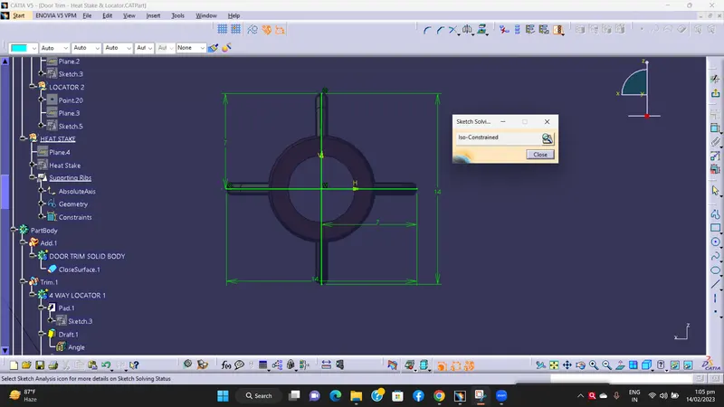
10) Heat stakes supporting ribs -
1) Class A surface check -
This surface is provided by styling team. This Class A surface is check by using boundary command, if there is irregularities then it is clear by using join command.
Then by using publication tool Class A surface is published.
2) Create tooling axis -
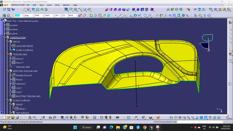
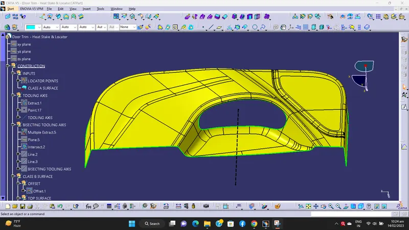
Tooling axis is a line of direction where core and cavity will open.
In bisecting tooling axis method, analyze the model manually or visually to see which direction is most suitable for tooling axis.
After checking all three direction, creating a point at the centre of the surface which is extracted.
At that point we creat a plane. Then by selecting this plane the Class-A surface is intersect.
Then two lines are drawn to the side faces of the intersected curves. Then we create one more line by bisecting this two line. Which our tooling axis.
Then published tooling axis by using publication tool.
A) BISECTING TOOLING AXIS -
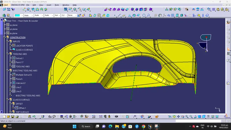
B) NORMAL TO THE SURFACE TOOLING AXIS -
3) Draft analysis for Class-A surface -
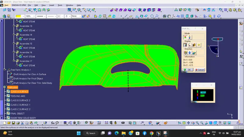
By changing the view mode to custom view, in the parameters – Material mode is selected. Then the feature of draft analysis is enabled.
Then the compass was activated and placed with the tooling axis by dragging the red pointer and then locked it.
Then, by selecting the quick analysis mode, the nominal value will be 3 degrees and checked for the components draft angle.
The green colour area shows that it satisfies the 3-degree draft angle.
If not satisfied then by using the running point tool the area is measured and then altered to get a successful draft for the created tooling direction.
4) Creation of Class-B surface -
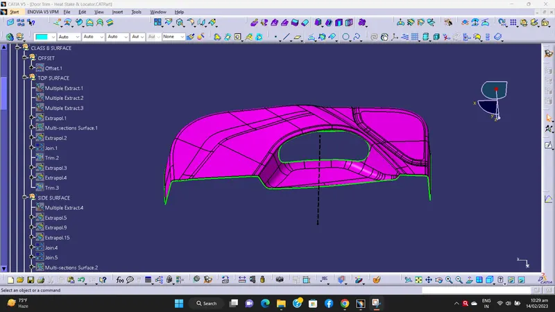
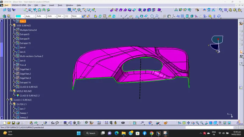
For creating the Class-B surface, we offset Class-A surface in downward direction by 2.5mm.
Then all the missing fillet patches or other surfaces are created by using multipale extract,extrapolate and trim command.
Finally, the required corners have been filleted by reducing the thickness value 2.5mm
Then published Class-B surface by using publication tool.
5) Creation of Class-C surface -
For the creation of Class-C surface, creating the boundary for Class-A surface.
Then by using the sweep command the surface was created by selecting respective boundary.
So get our Class-C surface.
After that we published Class-C surface by using publication tool.
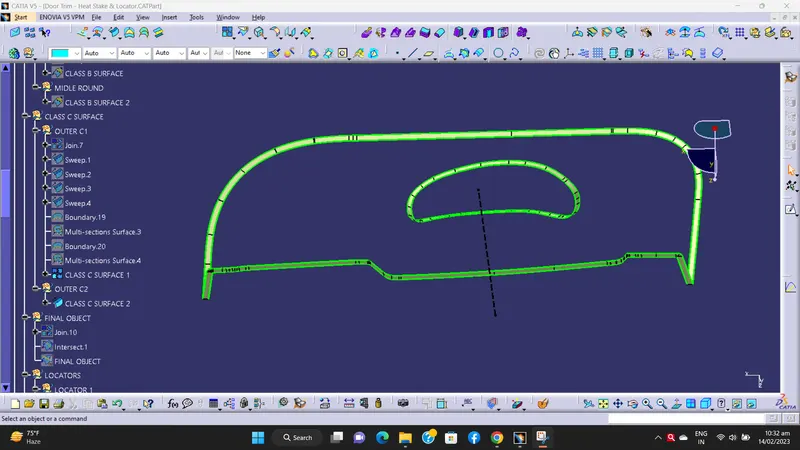
6) Final trimmed surface -
Now the Class–A surface is join with the surface which created by using sweep command.
Now this join is trimmed with Class-B surfaces.
We got required final trimmed surface.
Then published final trimmed surface by using publication tool.
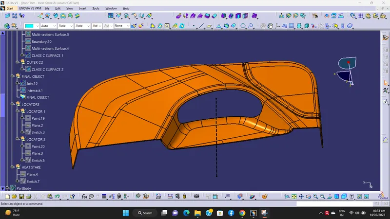
Draft Analysis For Final Object -
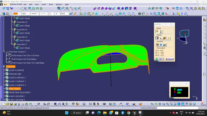
7) Convert surface to solid -
Now in part design workbench the final trimmed surface is converted into solid part by using close surface command.
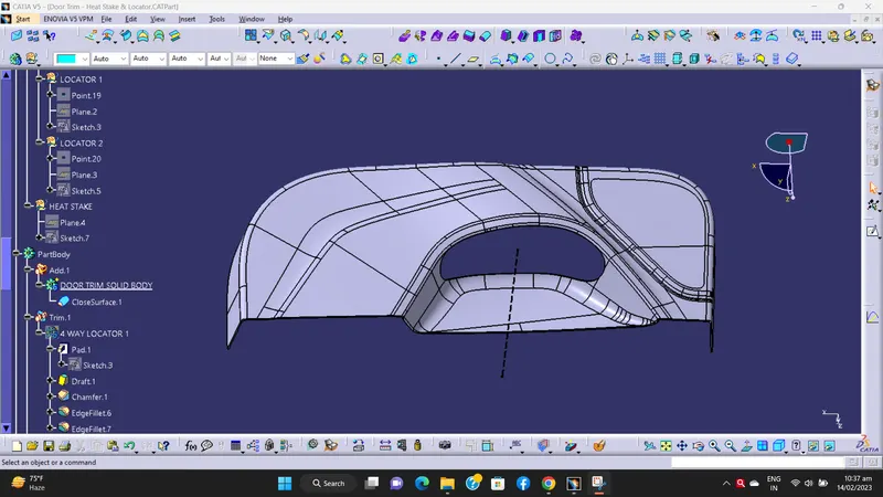
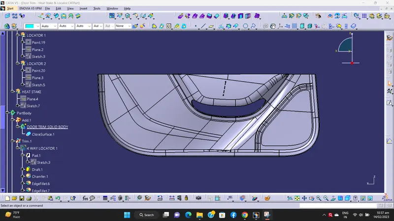
Draft Analysis For Solid Body -
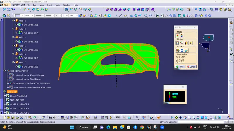
8) Creation of locators -
Locators work as a 3 - 2 - 1 principle which is basically to fix a component to be machined or to be placed in an ideal position. There are a total of 12 degrees of freedom, 6 rotational and 6 translational.
In this, we need to fix any 11 degrees of freedom permanently and anyone to be clamped or fixed temporarily. In this scenario, locators come into place. there are 4-way locators, 3-way locators, and more.
We creating locator as per giving locating points.
4 Way Locators -
a) Sketch 1 -
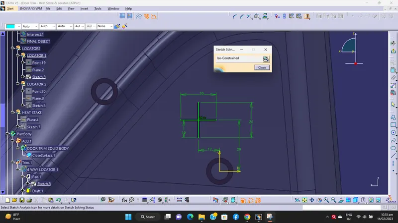
b) Sketch 2 -
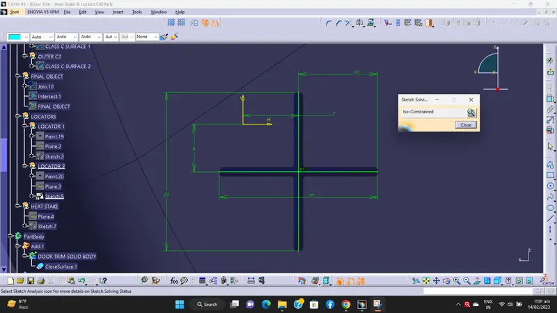
c) 4 Way Locators 1 -
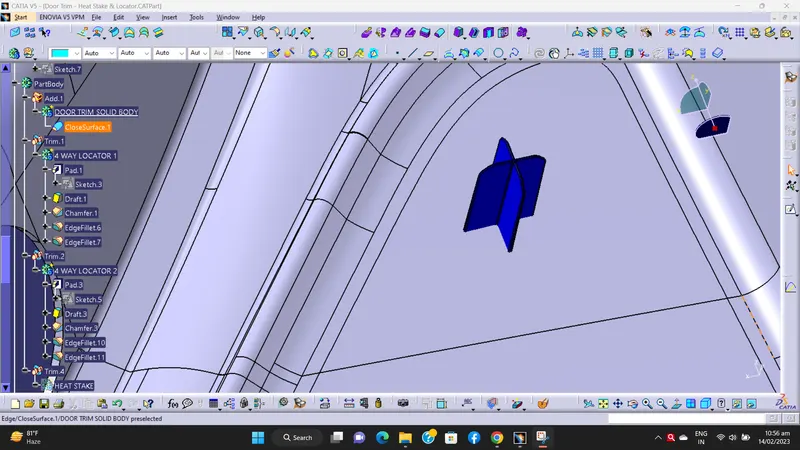
d) 4 Way Locators 2 -
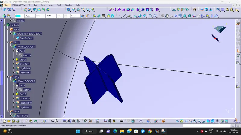
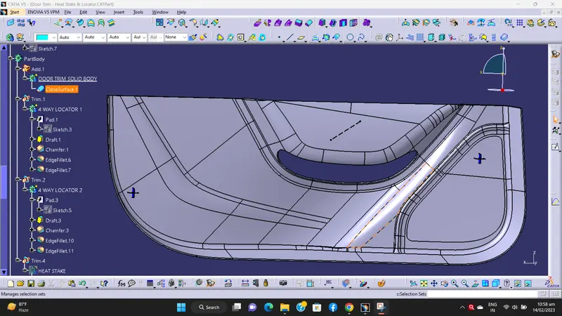
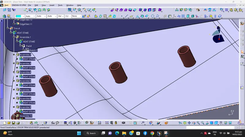
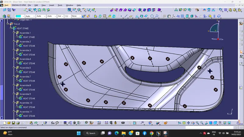
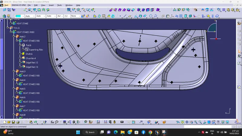
9) Creation of heat stakes -
This is also a fixing method of a plastic component to another dissimilar or similar surface or metal part. But in this process, both of them are joined together by thermal welding and can not be removed after that. A Boss or a stud is made on the plastic part, which is then protruded onto the opposite part and reformed after the locators fix the part temporarily and then thermal welded on the boss.
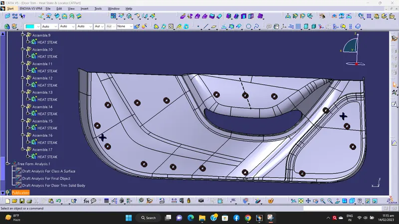
We creating heat stakes as per giving heat stakes points.
a) Sketch -
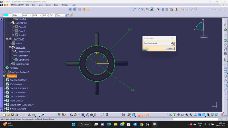
b) Heat Stakes -
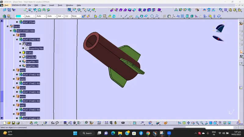
10) Heat Stakes Supporting Ribs -
a) Sketch -
b) Ribs -
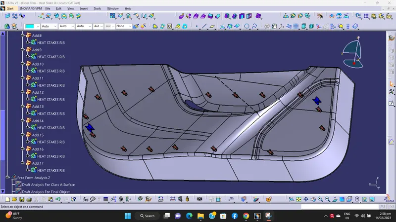
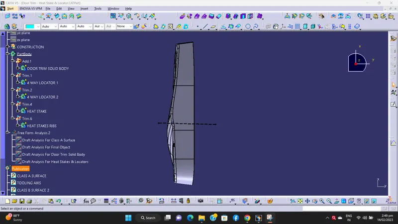
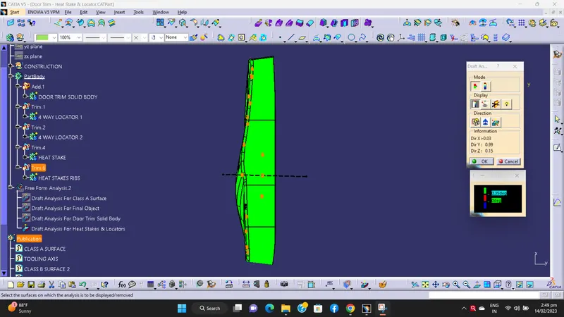
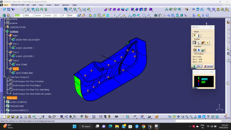
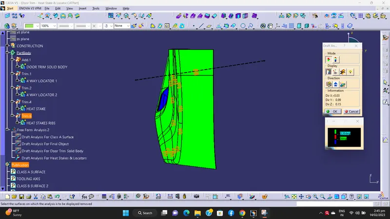
- Draft Analysis With Engineering Features -
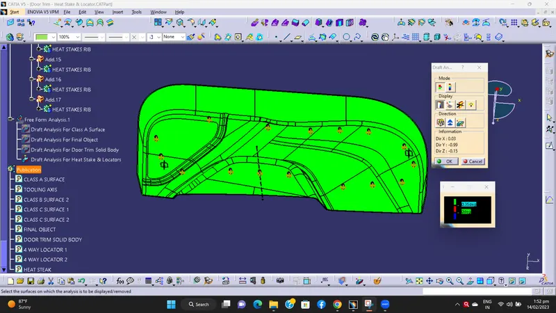
NOTE -
AS PER DISCUSSION WITH TECHNICAL SUPPORT MENTOR MR. DEVANAND, DRAFT ANALYSIS FOR ENHINEERING FEATURES, HEAT STAKES & LOCATOR IS NOT SHOWING ACCURATLY WITH 0.45 DEG ANGLE IN MY CATIA VERSION. THATS WHY I AM PERFORMING DRAFT ANALYSIS WITH 0.35 DEG ANGLE.
Various Orientations -
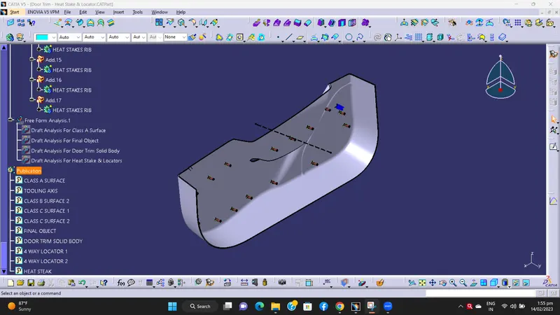
1) Isometric view -
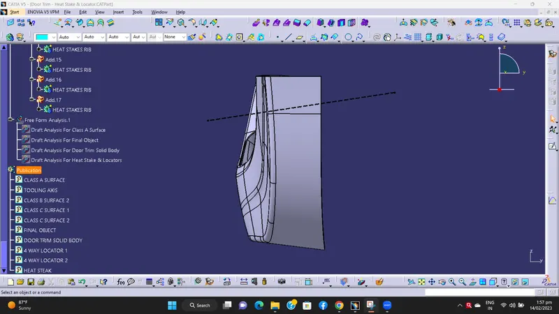
2) Front View -
3) Back View -
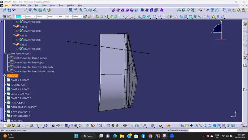
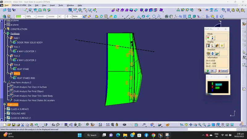
4) Side View RH -
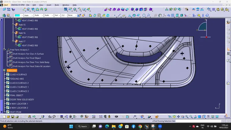
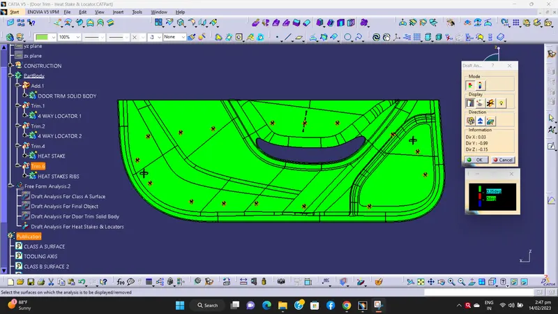
5) Side View LH -
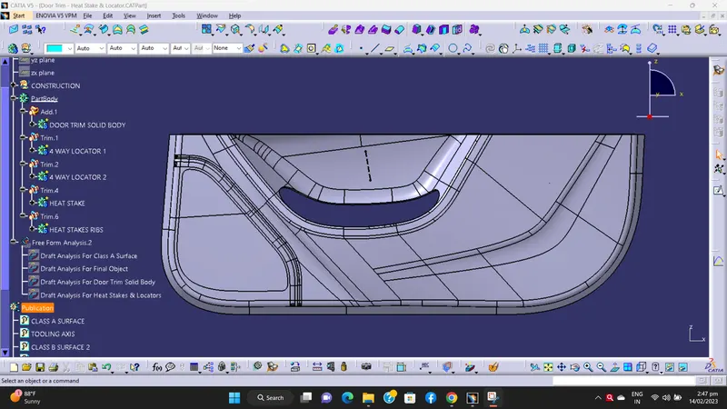
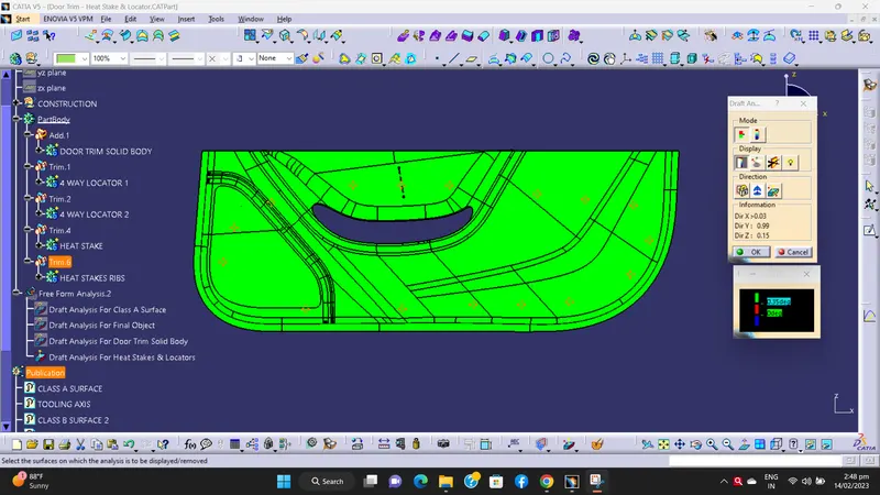
6) Top View -
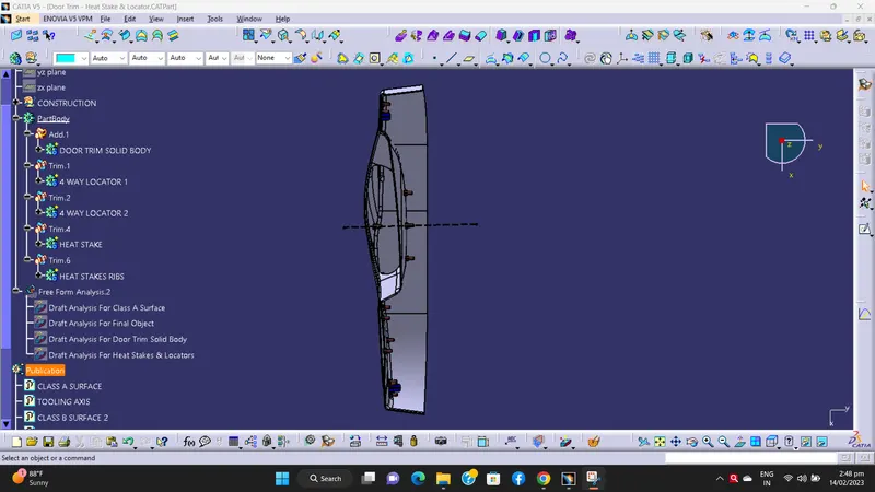
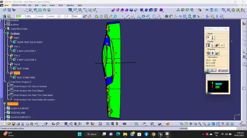
7) Bottom View -