Week 9 - Project 1 - Door Trim Lower with Engineering Features
Design overview
1)Create tooling axis
2)Create Class B surface.
3)Create Class C surface.
4)Perform draft analysis.
5)Create heat stakes and locators.
Tooling axis
1)It is defined as the direction in which the mould/core and cavity open.Selection of the direction of the tooling axis depends on the ease at which components can be easily ejected.
2)Check the connectivity and make sure there is no gap between the surfaces.
3)While creating a tooling axis please ensure to give the tooling axis on a flat length surface or the surface which have a hole on it.
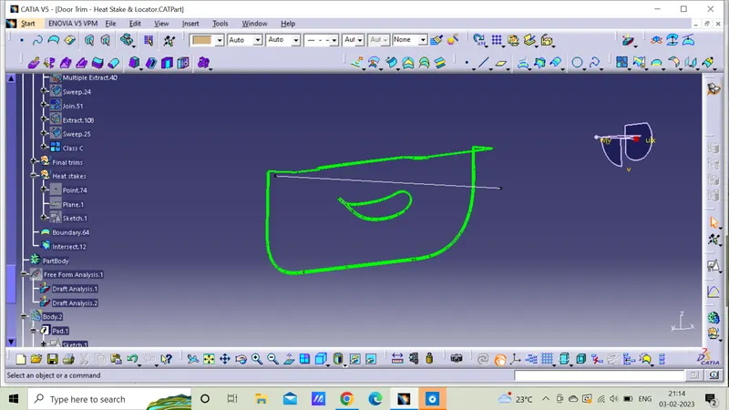
4)For the given class A surface Y axis direction is consider as the tooling direction.
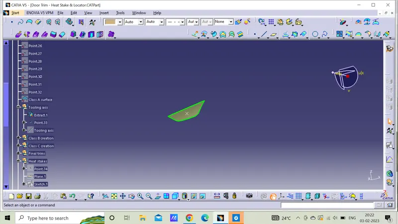
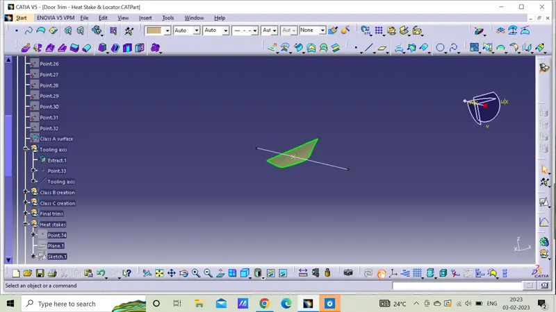
5)Create a point on the middle of the extracted base surface by using point on the surface command and use the line command to draw the line and it is extended to the required length.
Below are the images
Class B surface
1)In this case the surface below Class A is called core and the surface above is called cavity.
2)Class A is an aesthetic surface and B surface is called engineering surface.
3)In this case the Class B is offsetted towards inner side of the Class A for about 2.5mm.
4)Checked connectivity of the B surface,found few paches to be closed and it is done by using tools like blend,fill,multi-sections solid etc..,
5)Then it is further joined and checked for the connectivity of the surface.
Below are the images
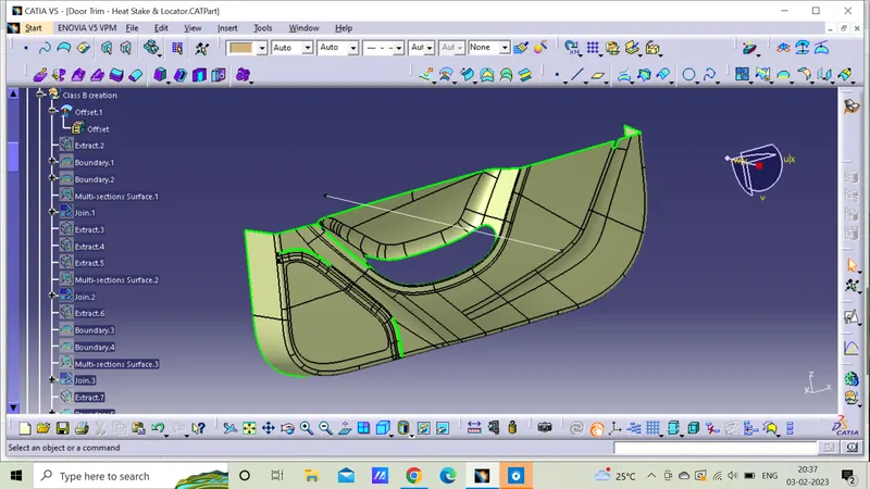
After patchwork,
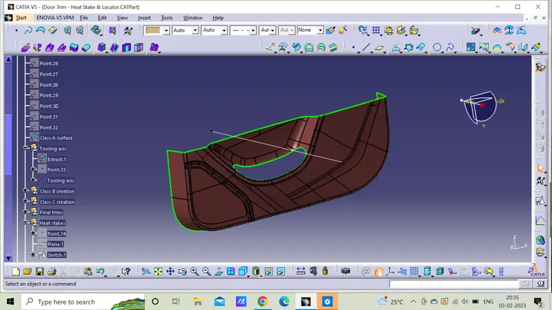
Class C surface
1)It is the connecting surface of Class A and B surfaces.
2)It is created by extracting the edges of the Class A surface by using the multiple extract tool for the extraction.
3)Create a sweep with reference to the curve and the reference surface with a 90 degree angle and give the inside direction,check for the continuity of the surfaces if there is any gap in it.
Creation of solid model
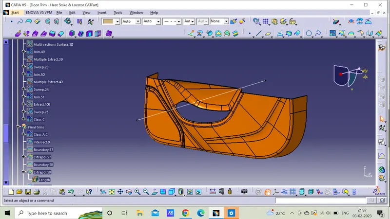
1)The surfaces such as Class A,C is trimmed with Class B surface and we'll get the final product.
2)Closed solid body is created by using the close surface on part workbench by selecting the final trimmed component.
Heat stakes and locators
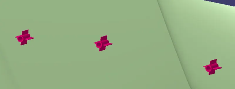
Heat stakes
Heat staking also known as thermoplastic staking is the process of joining two dissimilar materials together. In heat staking we use local heating and cooling to raise the temperature of plastic components and allow plastic reforming to be carried out. This reforming can be used in a wide variety of applications.
Several configurations for boss/cavity design are available, each with specific features and advantages. Their selection is determined by such factors as type of plastic, part geometry, assembly requirements, machining and molding capabilities, and cosmetic appearance.
In heat staking, we use local heating and cooling to raise the temperature of plastic components and allow plastic reforming to be carried out.
Heat staking can be performed using wide range of thermoplastic materials including polypropylene, ABS, polycarbonate and many others.
1)Thermal staking is an assembly method that uses the controlled melting and reforming of a plastic stud or boss to capture or lock another plastic or metal component of an assembly in place.
2)Heat stakes is used to arrest the degree of freedom of locators by 3-2-1 principle in automotive tooling design.
3)Proper design will produce optimum strength with minimum flash.
Guidelines for creating heat stakes
1)To find height,h=Wall thickness*5
= 2.5*5=12.5mm
height of the rib is 12.5mm.
2)To find thickness,w=0.4*t
=0.4*2.5=1mm
thickness is 1mm.
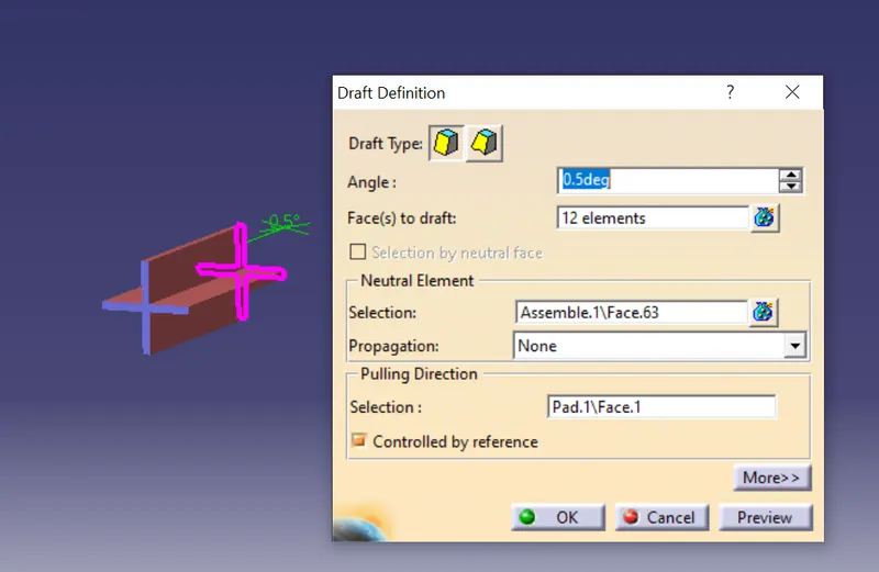
3)The draft angle given here is 0.5degrees.
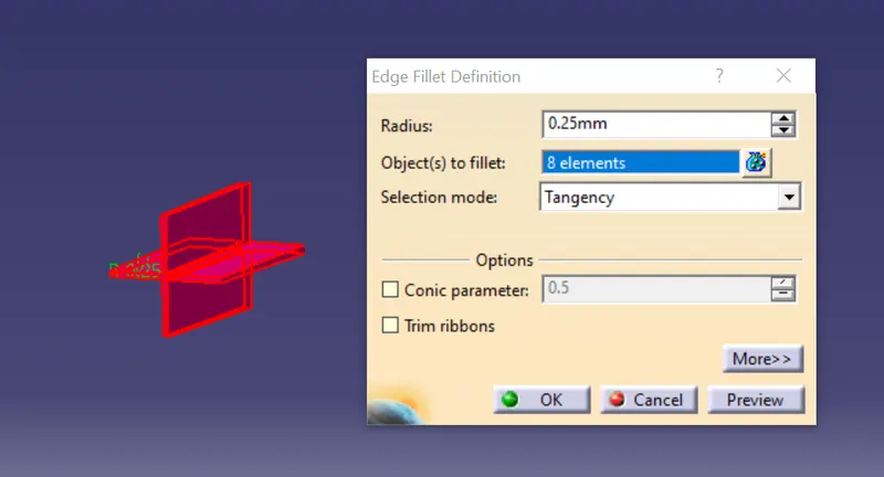
4)The fillet value given here is 0.25mm.
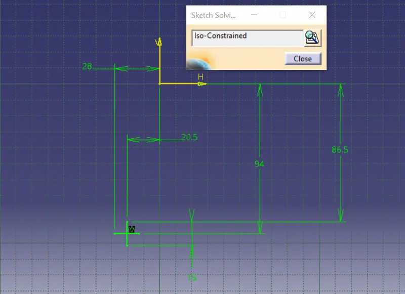
5)Minimum 15mm gap between the heat stakes.
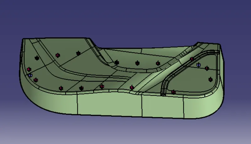
Multiple copies of the locator can be created by using copy and paste with special options then translate it by using suitable method.
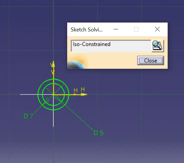
Sketch
Edge fillet
Locators
1)Locators are used to positioned the component in exact location and act as a guide for joining the two component.
2)Two types of locators are two and four way locators.
3)Locators can be designed as of the ribs.
4)Initially it is created by forming a sketch and then it is extruded to the required height as per the requirements.
5)The locators will follow the same rib design guidelines and will be given a minimum draft of 0.5 degrees and a minimum fillet of 0.2mm and an entry chamfer of 3mm.
6)The ribs should be spaced with height of 3:1 or 2:1 and less than 5* wall nominal thickness.
7)Multiple copies of the locator can be created by using copy and paste with special options then translate it by using suitable method.
Locator sketch
Draft angle
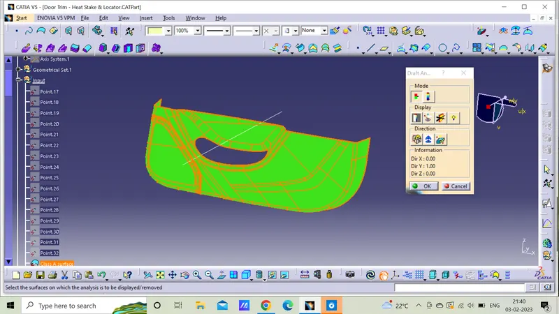
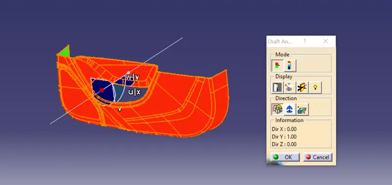
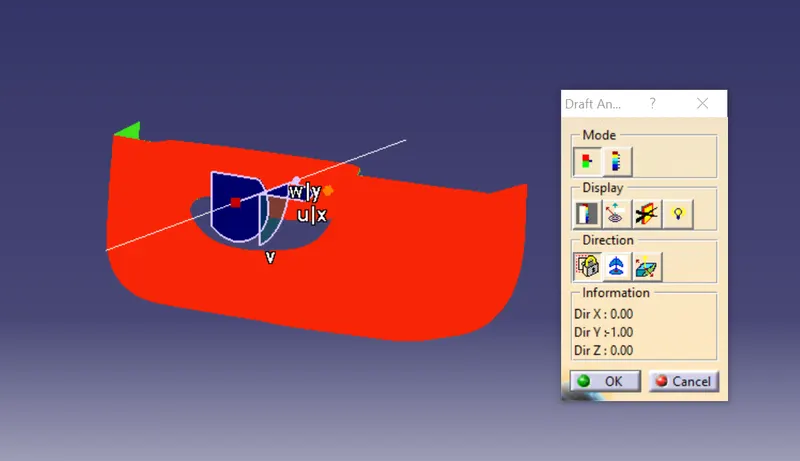
Draft analysis
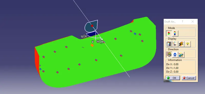
1)Draft allows for the component to release from the mould, most parts or applications require a minimum of 0.5 to 1 degree draft angle and 3 dgree draft angle is widely used as per the norms.
2)Insert –analysis-feature draft analysis.
3)Change the material mode to customize mode before moving to the draft analysis.
4)Align the compass in the tooling axis and click on the lock symbol,we'll get a point select the point it shows the draft value if required we can adjust the value.
5)Clicking on the surface by using flipping tool,we can the flip the directions and change the colours by flipping direction.
6)Analysis under the running point will show the exact details of the surface deg direct at each and every point of the surface.
(Green above 3degrees)
(Blue 0-3degrees)
(Red below 0degrees)
Advantages of draft
1)Reduces wear and tear.
2)Reduces the chance of damage due to friction.
3)Reduces the overall cooling time by lessening for unconventional ejection setups.
Draft analysis on Class A
Draft analysis on solid model
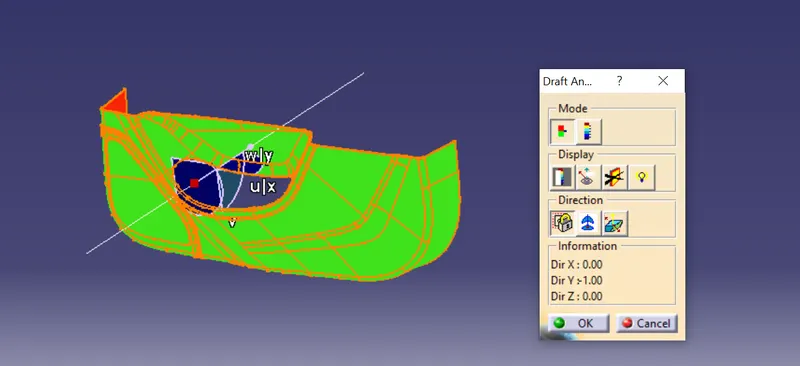
Draft analysis on final product
Conclusion,
Designed door trim lower with engineering features such as heat stakes and locators.