Week 8 - Challenge 6 - Core & Cavity Design
Design overview
1)To create core and cavity design for the switch bezel.
2)To perform draft analysis.
Tooling Axis
1)Initially it is formed by the bisecting method for this model.
2)The view of the model to the X direction and creating the tooling Axis,Using the intersect in ZY plane to get the boundary lines.Then these two lines are bisected to get the tooling axis for the X direction.
3)It is the axis in which core and cavity gets open and close.
(Bisecting Method)
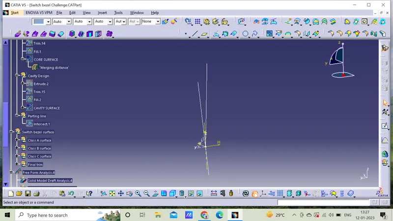
Below line represents the Tooling axis
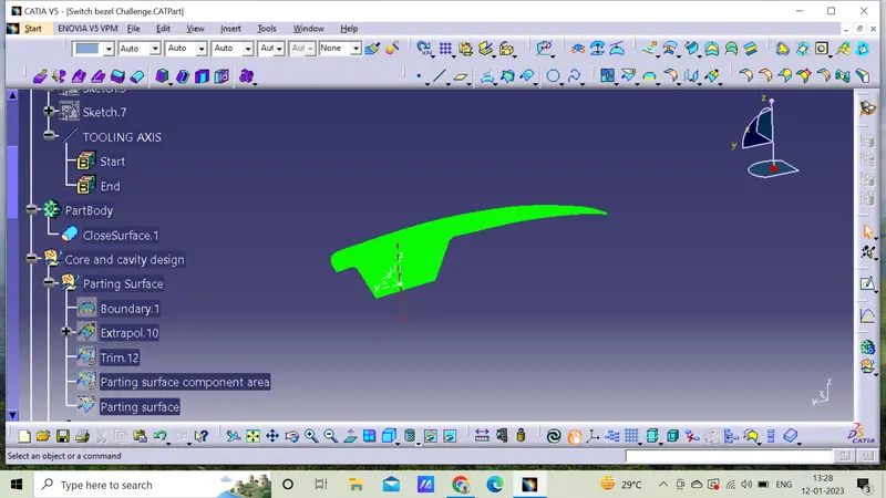
Parting Surface
1)It is a surface that separates the mold block into two parts.
2)During the process two halves are pressed tightly from a sealed hollow to avoid the melt flow leakage and maintain certain holding pressure that pressured surface is called parting surface.
3)It is the biggest outline of the part.
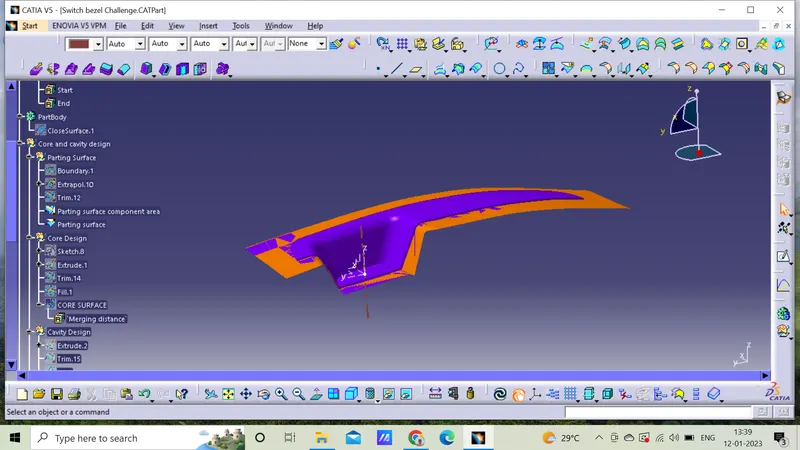
Parting line
1)It is the two halves of the mold meet around the parameter of the part.
2)It is the line which determines the direction of mold opening and easy ejection throughout the process.
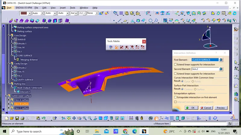
Core design
1)It is the male part of the mold it forms internal shape of molding.
2)It is the raised part of the mold.
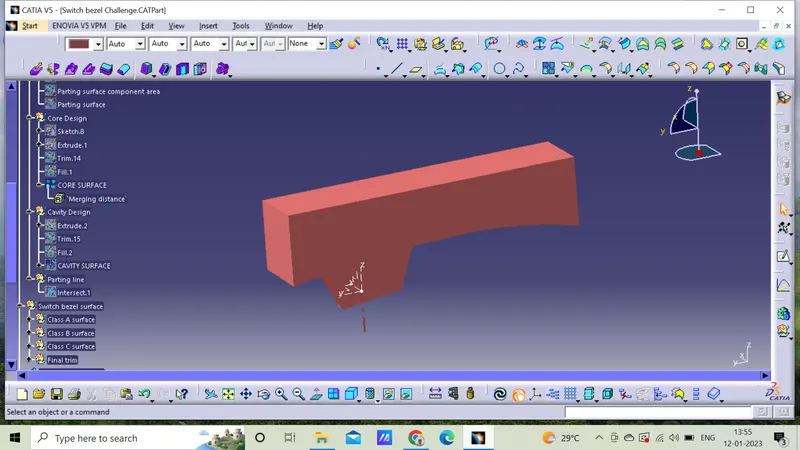
3)The core design is started with extracting the parting surface that becomes the datum for the core and cavity.
4)At first Class A is extrapolated and trimmed with Class C surface.
5)Later on,trimming Class B with (Class A,C) will be the parting surface,extruding the sketch towards the tooling axis and trim it with parting surface.
Final output below
Cavity Design
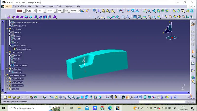
1)It is the female part of the mold which forms external molding.
2)It is the decessed part of the mold.
3)It is the area where injector and filling of molten plastic happens.
4)The cavity block is prepared by trimming extrapolated Class B surface and same profile used in core for rectangular block to extrude along the tooling direction.
Draft analysis on solid model
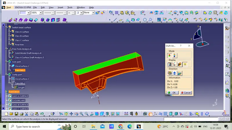
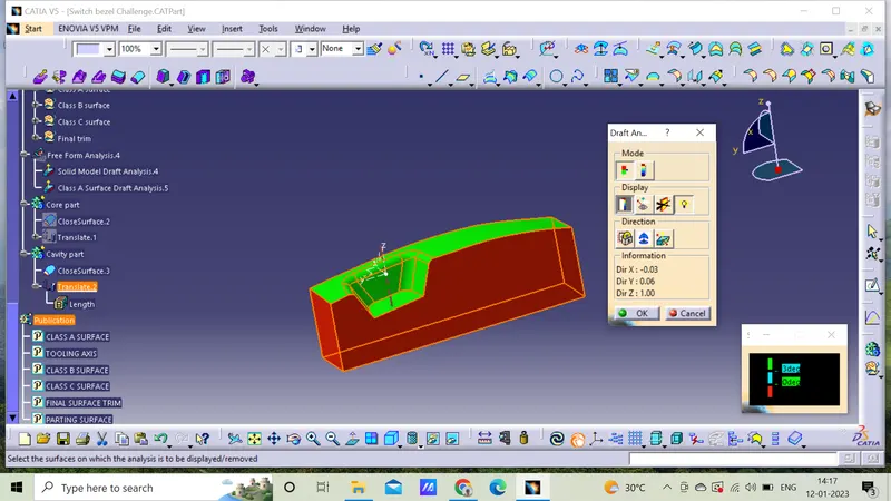
1)It is technique used to analyze whether our part model created in CAD is manufacturable that is based on draft condition applied.
2)A draft angle is provided to each and every area of the component in order to get easy removal of the component from the tool.
3)These type of analysis is performed and based on the colour ranges on analyzed elements.
Final output is below as follows.
Green above-3 degrees
Red below-0 degrees
Core part of draft analysis
Cavity part of draft analysis
Iso view
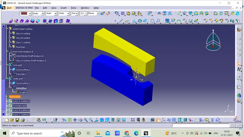
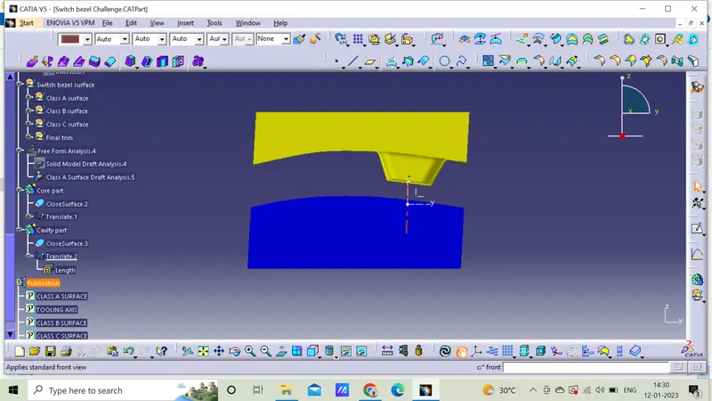
Front view
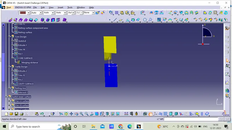
Left view
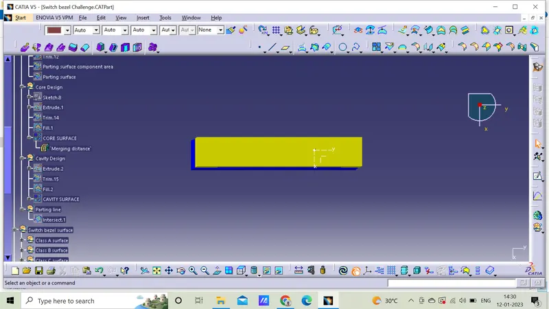
Top view
Conclusion
Core and cavity block for switch bezel is created.