Week 8 - Challenge 4 - Bumper
Design Overview
1)To create tooling axis.
2)To create Class B surface.
3)To create Class C surface.
4)Joining of Class A,B,C surfaces.
5)To create draft analysis.
Tooling Axis
1)In this case fog lamp hole is considered as the perpendicular axis for the tooling axis.
2)Initially,extracted the hole,created the points across the walls and drawn a line along Y axis.
3)Formed an intersection between these directions and created two lines along X axis.
4)The tooling axis is created by bisecting the two lines.
5)Tooling axis is formed.
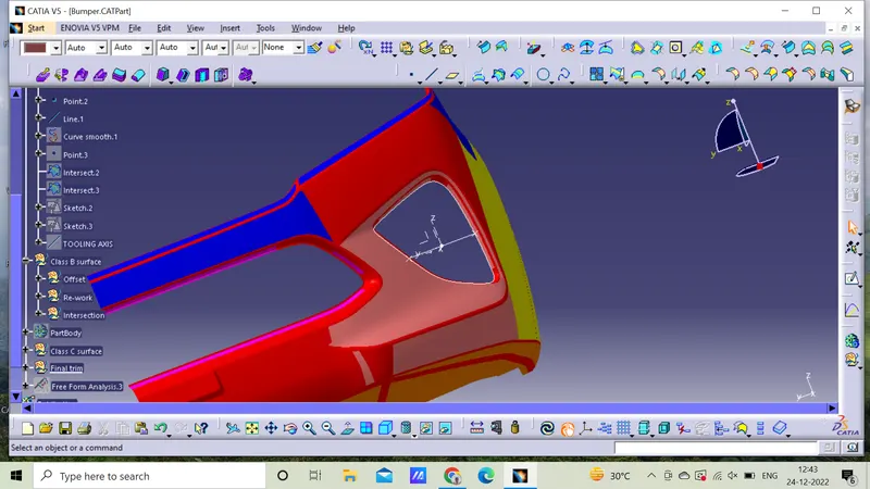
Two lines along X axis
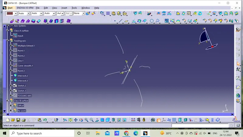
Tooling axis
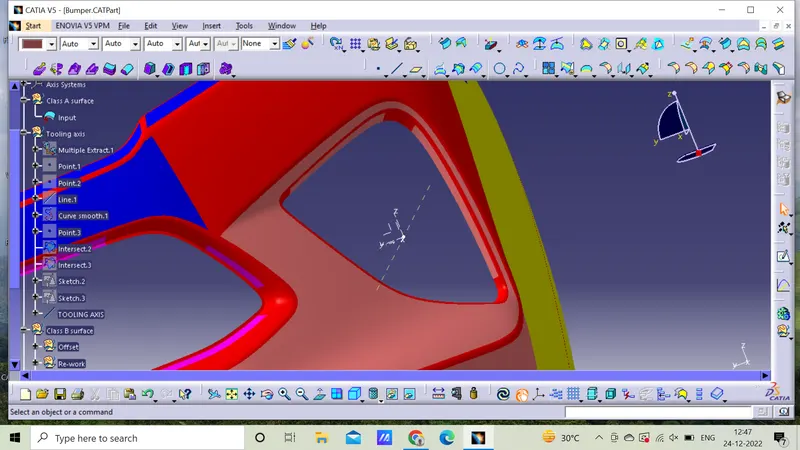
Class B surface
1)Class A surface is offseted by 3mm and formed B surface.
2)B surface has few issues and it is corrected by using (Multi sections,sweep etc..,).
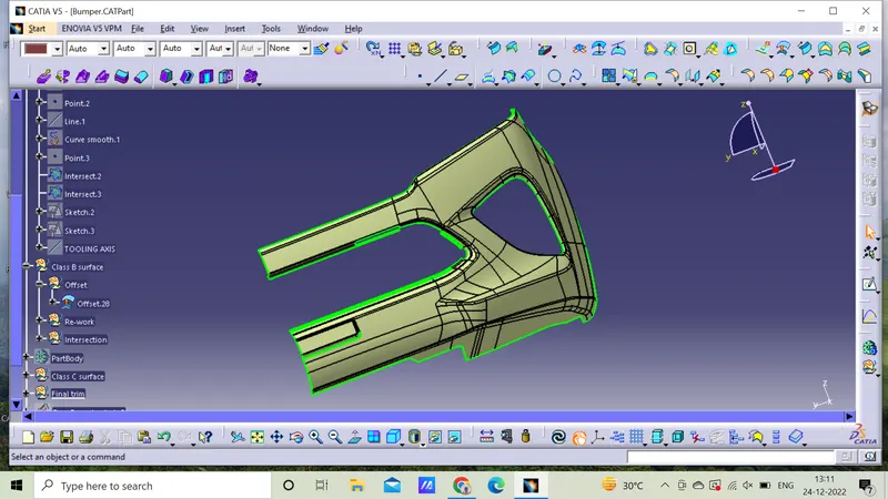
Class B surface
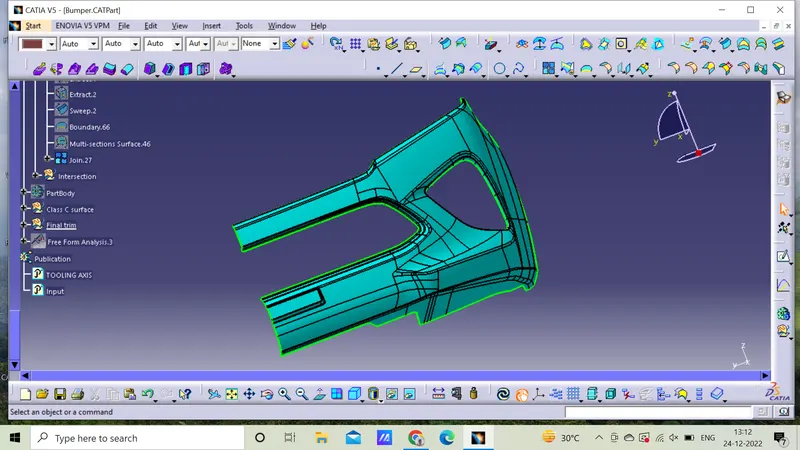
Class C surface
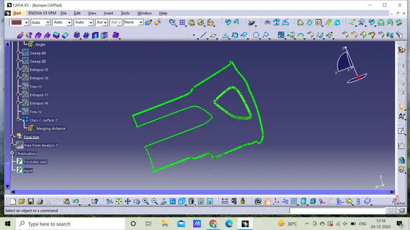
1)It is formed by creating boundary across A surface as reference surface.
2)Sweep is used for the creation of C surface.
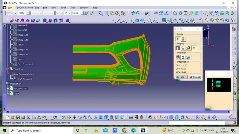
Draft analysis
1)Draft angles is must for injection molded parts and it reduces the risk of damages.
2)It is done after formation of tooling axis to check whether draft angle is maintained or not.
3)Green colour represnts the positive and red represents the negative tooling direction.
4)In this case side walls do not carry any draft angles.
5)Here the draft angles are 3 degrees and it is formed.
Iso view
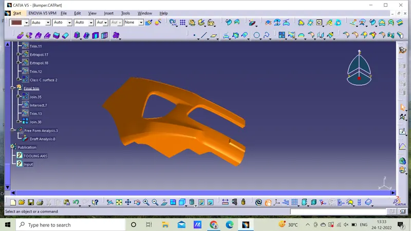
Front view
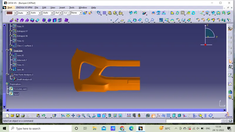
Left view
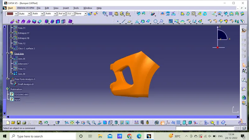
Top view
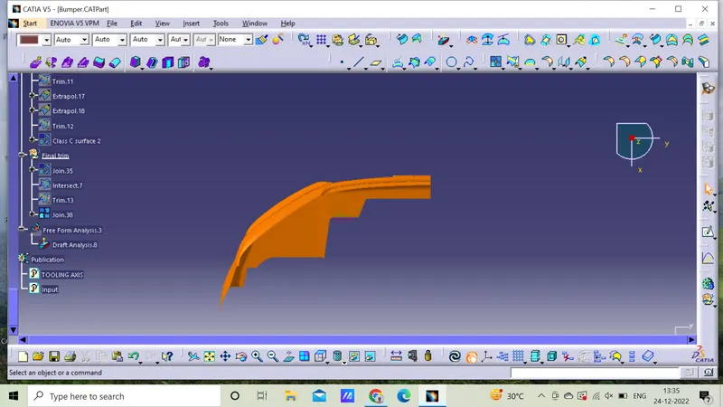
Conclusion,
Created the bumper by using Class A surface and formed tooling axis,draft analysis.