Week 8 - Challenge 3 - Coin Holder Design
Design overview
1)To create tooling axis.
2)To create Class B surface.
3)To create Class C surface.
4)Joining Class A,B,C surfaces
5)To perform draft analysis.
Tooling axis
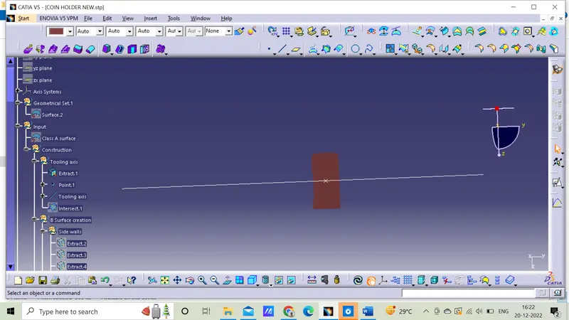
1)Tooling axis is created by bisecting lines,but in this case where it has bin usually line is used.
2)Initially for this model created a point on the base surface.
3)Tooling axis should be perpendicular to the base area.
4)Line is drawn in Y direction and extended to required length that is perpendicular to the bin,axis system is also created.
5)Tooling axis is created and named in geometrical set.
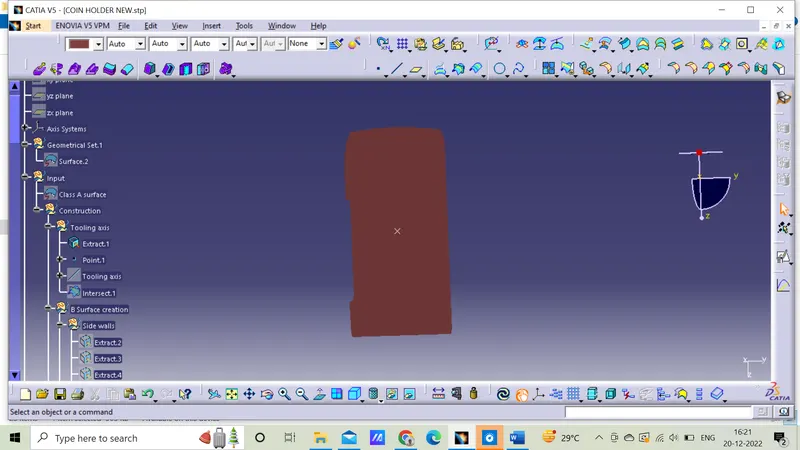
Line along Y axis
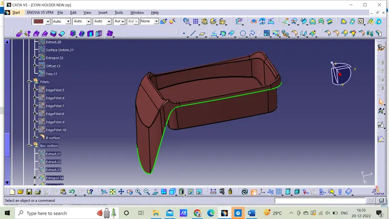
Class B surface
1)The Surface at which features like Side walls, base, top walls and Outer walls etc. are made to support external mountings is called Class B Surface.
2)It is made by extracting the Class A surface,offset it to desired thickness and trimming them together.
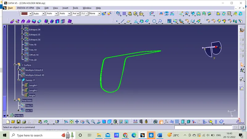
Class C surface
1)It is the connecting surface between Class A and B.
2)Extracting the edges from Class A and creating way for sweep in Class C surface it is kept 90 degree horizontally.
Draft analysis
1)The final draft analysis are green colour represents the angle above 3degrees and the red colour indicates below 0 degree.
2)The surfaces with green can be easily manufactured and the red colored cannot be ejected.
3)During draft analysis, it is observed that bin walls are having a 90-degree angle with the base, There is no minimum draft given to the walls.
4)Draft analysis is done on the final component to check manufacturing ability. The walls of the bin are having zero draft angle with the tooling axis. This will be ignored since it is given on the Class A surface.
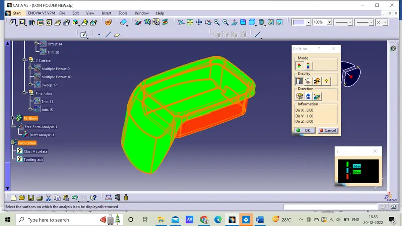
Below 0 degree
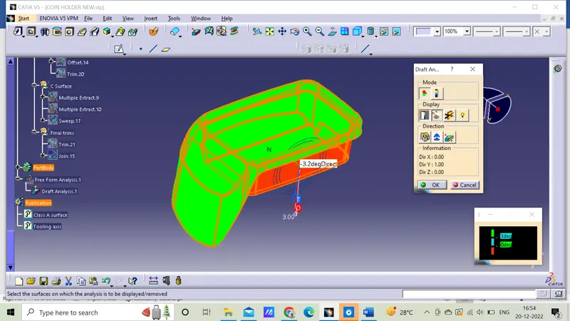
Iso view
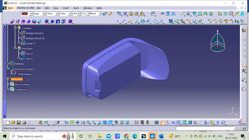
Front view
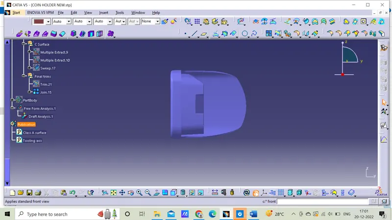
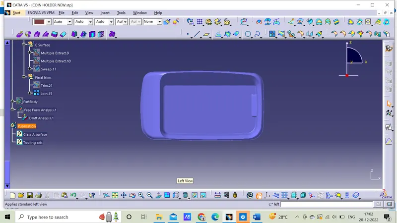
Top view
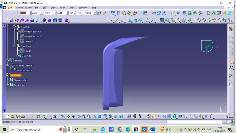
Left view
Conclusion
Solid component is formed and draft analysis is performed is performed by using Class A surface.