Week 8 - Challenge 2 - Switch Bezel Design
Overview
- Creating tooling axis.
- Creating Class B surface.
- Creating Class C surface.
- Joining Class A,B,C surfaces and further it is closed.
- Performing draft analysis on the component.
Tooling axis
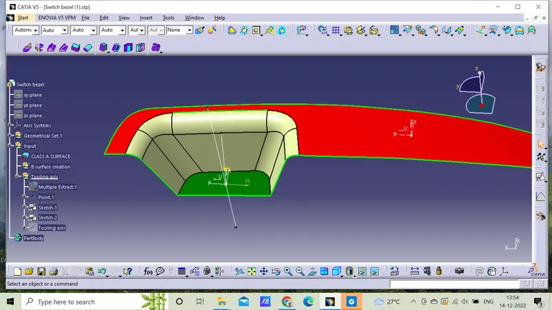
1)Reference point is created along the surface zero and axis system is created.
2)X and Yaxis along the class A is created for the tooling axis(i.e..,ZX and ZY plane) respectively.
3)Tooling axis is created by bisecting two lines and it is formed.Further Class B is developed.
4)Tooling axis determines the direction of the class C boundary with draft direction.
5)While viewing from the tooling axis all the parts should be easily visible such that it provides an idea for manufacturing process.
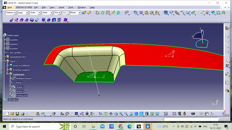
Along ZX and ZY planes
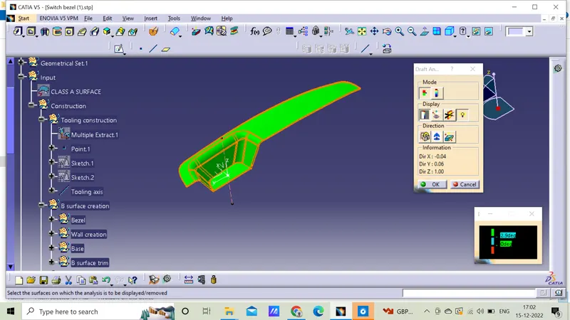
Draft analysis
1)Initially,go to analysis>feature draft analysis,further it has to be changed to material mode.
2)The axis system is enabled and aligned along with tooling axis direction and it is locked.
3)The nominal value will be 2.9 degrees and checked for the component's draft angle.
4)The green coloured area shows the material is satisfied if not it is altered to the required degree for the further process.
5)Finally the draft analysis is created.
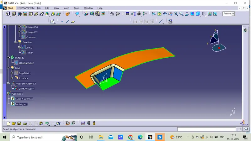
Class B surface
The class-B surface is the second surface that has a certain thickness from the class-A surface. this surface contains engineering aspects of a model.
Class C surface
Class C is often specified for interior surfaces not readily visible, surfaces that will be covered by another part when assembled, or surfaces.
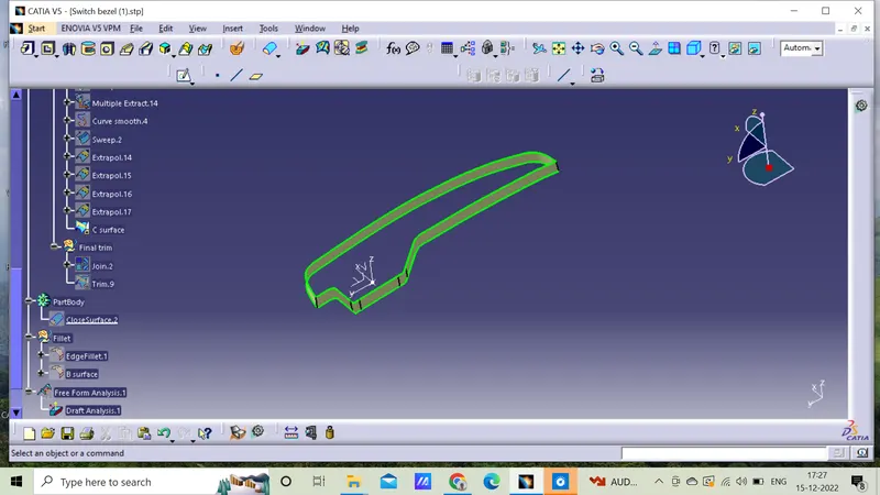
Iso view
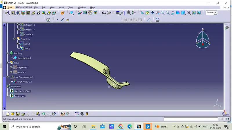
Top view
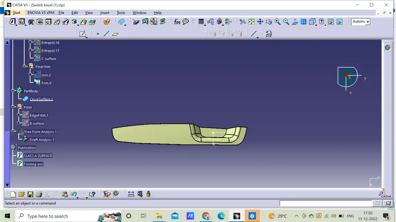
Left view
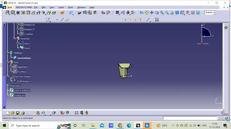
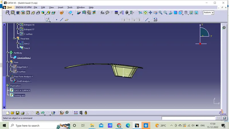
Front view
Conclusion
Switch bezel plastic component is successfully created and performed draft analysis by using the Class A surface.