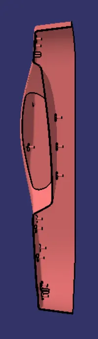
Week 9 - Project 1 - Door Trim Lower with Engineering Features
AIM: Create the Door Trim Lower Plastic component through the given Class-A surface
OBJECTIVES:
- Create a solid body using the given class-A
- Create the heat stakes for door trim considering the design rules
- Create the locator for door trim considering the design rules
INTRODUCTION:
In this project, we are creating the Door Trim Lower Plastic component through the given Class-A surface using the Catia software, from that we create a Class-B surface with a thickness of 2.5 mm throughout the component. And Class C is also created using both Class A & B. Draft analysis is also conducted with a minimum of 3 degrees as standard. Make sure that the surface model is completely closed before converting into solid.
Draft
In engineering, the draft is the amount of taper for molded or cast parts perpendicular to the parting line. It can be measured in degrees or mm/mm (in/in)
- Drafts (or taper) in a mold, facilitate part removal from the mold. The amount of draft angle depends on the depth of the part in the mold, and its required end-use function.
- The draft is in the offset angle in a direction parallel to the mold opening and closing.
- It is best to allow for as much draft as possible for easy release from the mold. The minimum taper angle is 0.5 to 1 degree but 3 degrees is a widely accepted norm.
- The mold parting line can be relocated to split the draft in order to minimize it. If no draft is acceptable due to design considerations, then a side action may be required at a greater expense in tooling.
Draft Analysis
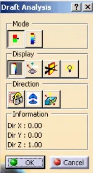
Displays a color gradient on the faces of selected bodies to help evaluate the manufacturability of your design. Select the bodies to evaluate and the axis to define the direction. Use the options to refine the gradient display. In Catia, we use the feature draft analysis tool for this.
Tooling Axis
It is the direction in which the mold or core and cavity open is the tooling axis
Bisector Method: It is a common method used to create a tooling axis for Class-A surface, firstly select the direction in which tooling is difficult there may be one or two directions on a single surface. Then, create an intersecting curve with respect to the surface by taking a plane as a reference and draw lines that coincide with the intersection curve where the draft occurs, then bisect these lines to get the tooling axis. Use this method in another direction if needed. Finally, bisect those axes to get the tooling axis for the surface.
Heat Stake
Heat staking also known as thermoplastic staking is the process of joining two dissimilar materials together. The component used for this process is heat stake. In heat staking, we use local heating and cooling to raise the temperature of plastic components and allow plastic reforming to be carried out. This reform can be used in a wide variety of applications.
Locators
Locators are used to arresting the DOF of the component we are machining. There are 12 DOF for every component 6 linear and 6 rotation and these motions are arrested by locators.
There are two types of locators
1) 4-way locator
2) 2-way locator
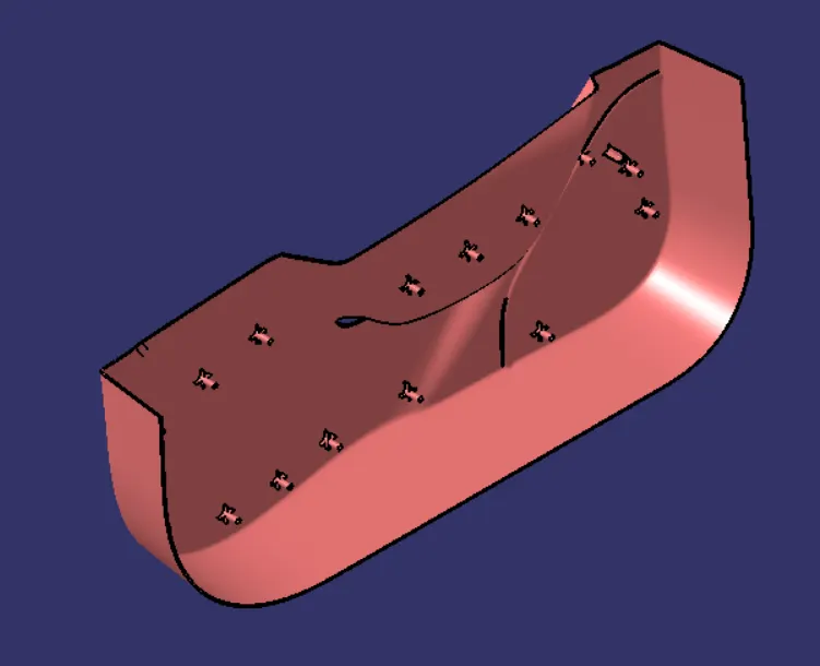
In our case, I have attached two 4 way locators and 16 heat stakes
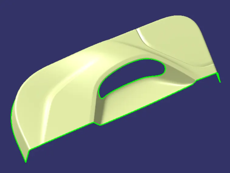
Class-A
Class-A surface given to us
PROCEDURES
Step 1 - Creation of Tooling Axis
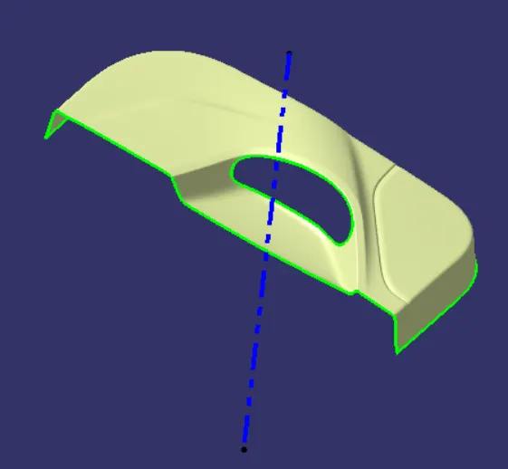
On this surface, we are going with the trial and error method by selecting a random point on the surface. For that, I take the center of the flat surface as a reference point as shown below. Then extend it in the Y direction, ie taken as the tooling axis for this surface.
In this design, the bisector method is more difficult compared to this method.
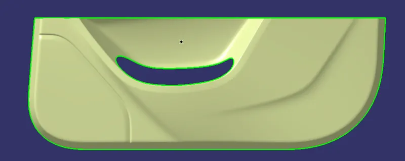
Step 2 - Draft analysis of Class-A Surface
Draft analysis is conducted with a limiting value of 3 degrees. By this, we confirm whether our trial and error method for selecting the tooling axis is correct or not.
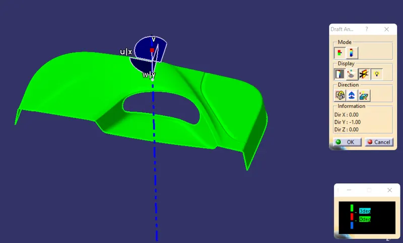
Draft more than 3 degrees shown as green. The draft below 0 degrees is shown as blue. Draft between 0 and 3 degrees shown as red.
Step 3 - Creation of Class-B Surface
In this, the Class-A surface is offset to 2.5 mm but we may face some gaps occur. Close the gaps using the fill and multi-section commands. Finally, join all the filled surfaces with offset surface into a single surface using the join command.
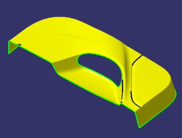
Step 4 - Creation of Class-C Surface
Class C Surface is the connection surface of Class-A and B. For this, multi-extract the boundaries and then extend them using the sweep command separately. Join the swept surface into a single one using the join command.
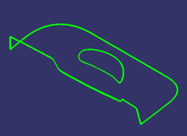
Step 5 - Final Trim:
Class-A + Class-C
In this, we connect both Class-A and C using the join command and make sure there is no gap between A & C.
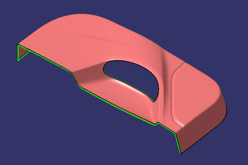
Class-A + Class-B + Class-C
This made the final output from the surface workbench by trimming all the unnecessary portions and check the surface is completely closed.
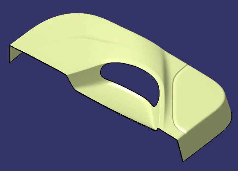
Step 6 - Creation of Heat Stakes & Draft Analysis
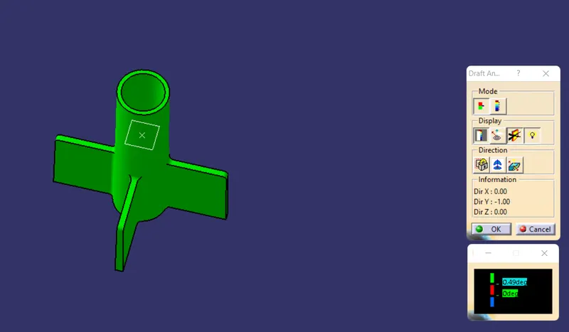
Draft Analysis shows that a given body have a draft of 0.49 degrees. The given draft is 5 degrees but it may vary at different points so we put 0.49 degrees for draft analysis.
Step 7 - Creation of 4-Way Locator & Draft Analysis
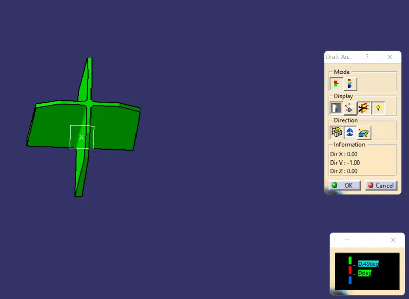
Draft Analysis shows that a given body have a draft of 0.49 degrees. The given draft is 5 degrees but it may vary at different points so we put 0.49 degrees for draft analysis.
Step 8 - Draft Analysis of Final Plastic Component
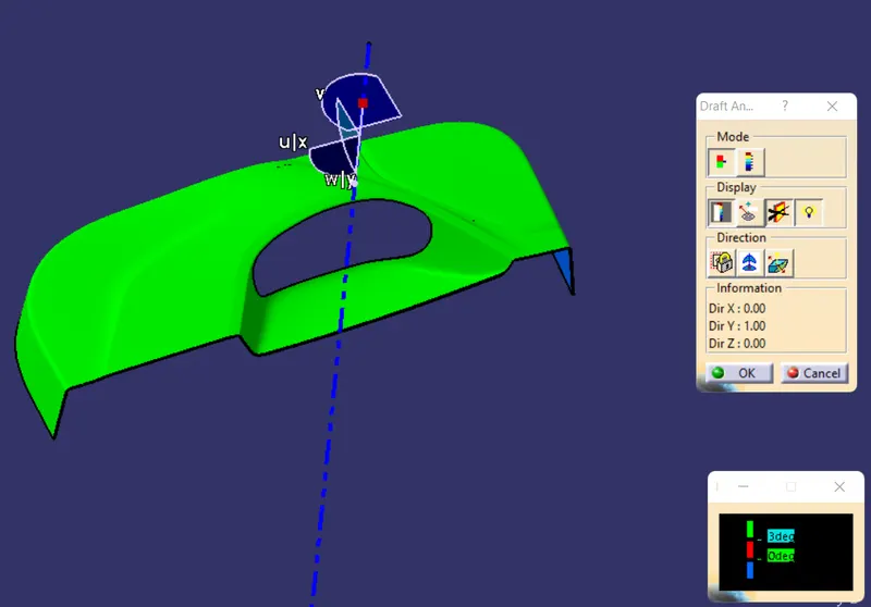
Draft more than 3 degrees shown as green. The draft below 0 degrees is shown as blue. Draft between 0 and 3 degrees shown as red.
CONCLUSION:
Heat Stakes and the locators for the door applique are created from the given Class-A
1. Isometric View
2. Front View
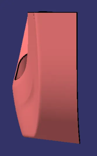
3. Side View
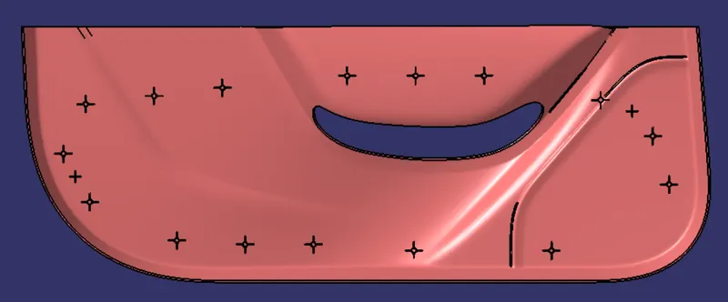
4. Top View