Design and Development of Door Trim Lower with Engineering Features on it
The Objective of this Project is to - (a) Create the Door Trim Lower Plastic component through the given Class-A surface. (b) Create the Heat Stakes and the locators considering the design rules mentioned in the video for the door applique.
the complete step-by-step procedure is as following:
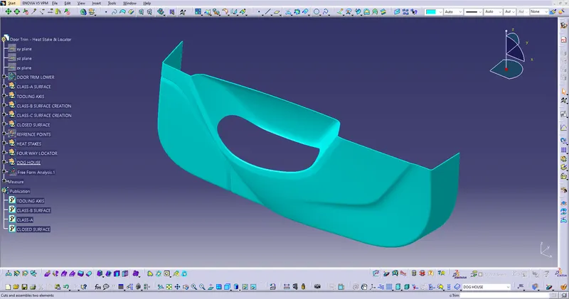
| CLASS-A SURFACE. |
This is the Surface that will be the Visible Surface to the consume. The asthetics and properties of this surface is not to be altered. |
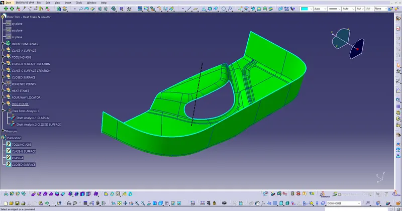
| TOOLING AXIS & DRAFT ANALYSIS OF CLASS-A. |
Draft Analysis of Class-A surface |
| CLASS-B SURFACE CREATION. |
This is the Surface that goes under the housing, and also cosists of Engineering Features like Ribs, Screw Boss, Dog House, Stiffners of the part. |
| CLASS-C SURFACE CREATION. |
Class-C surface is the surface which connects Class-A and Class-B to form a closed Surface. |
| CLASS-A + CLASS-C SURFACE CREATION. |
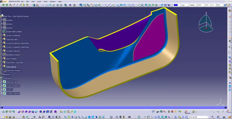
Class-A and C are Joined to Create a Single Surface before trimming it with Class-B Surface. |
| CLOSED SURFACE. |
Closed surface obtained by Trimming Class-A + C & Class-B. |
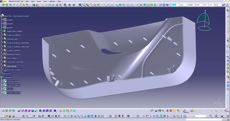
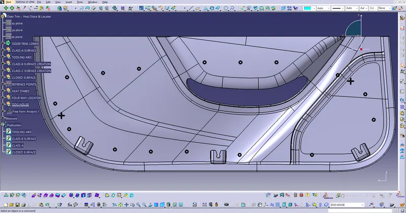
| FINAL COMPONENT WITH ATTACHMENT FEATURES. |
Door Trim With the B-Side Engineering attachment Features like Heat Stakes, Four-way locator, Dog house. |
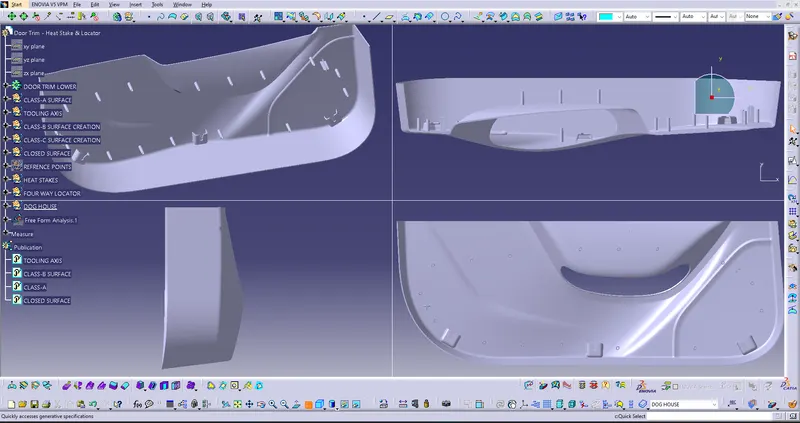
| ALL VIWES OF THE FINAL COMPONENT. |
Isometric, Side, Front and Top view of the Door Trim Applique. |
| DRAFT ANALYSIS OF THE FINAL COMPONENT. |
Draft Analysis of the Final Door Trim Applique. |
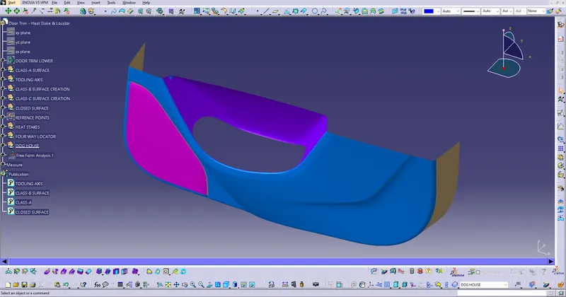
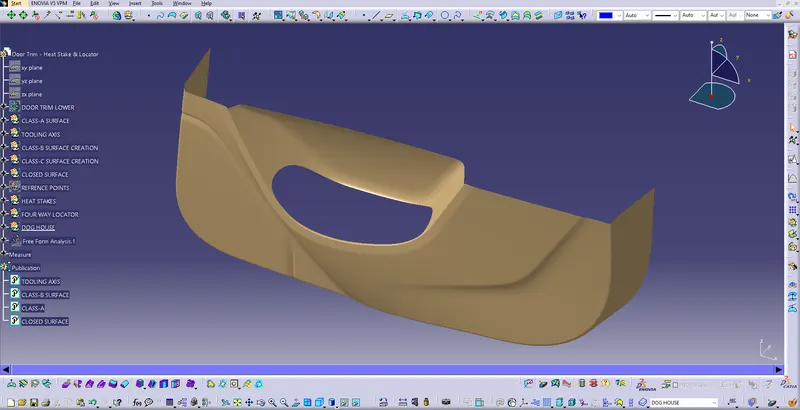
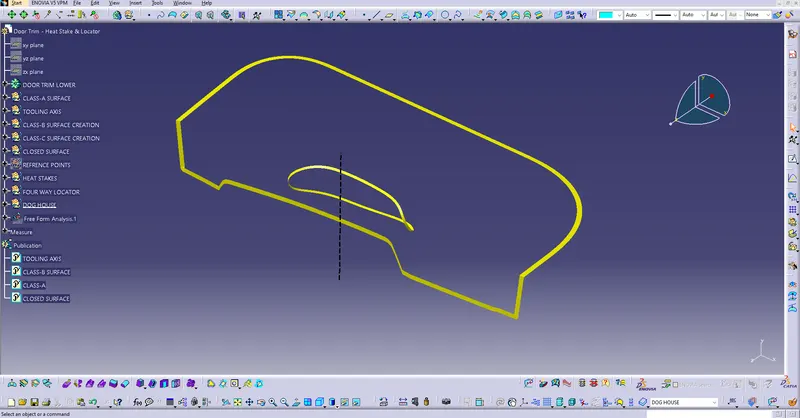
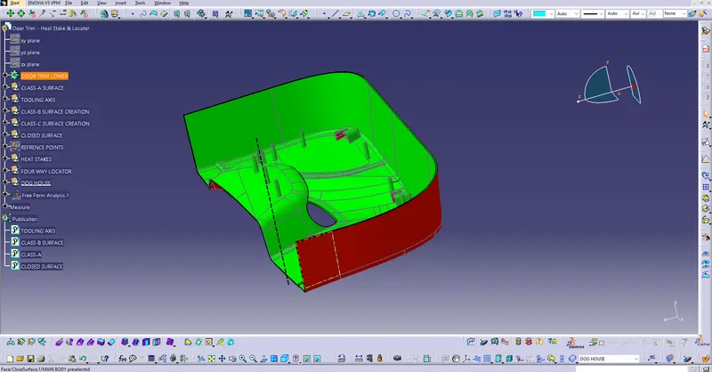
TOOLING AXIS CREATION:
Creating Tooling axis is one of the Important factor of the creation of the component CAD Part. Tooling axis can be created using Bisecting Method by Bisecting two axis clearing the draft angles both in X & Y Direction. Tooling Axis is very important part while designing the CLASS-B. The determination of the direction of Tooling Axis depends on the phases of the surface. In this part a line was created in the Y-Dirction, it cleared the draft analysis of the part, so the line was used as the Tooling Axis. (shown in the picture below). The Bisecting Method of creating the tooling axis is first we create two lines to clear the draft analysis on both components X & Y. When we get both the lines we simply need to bisect it. The line formed by Bisecting those lines will be our Tooling Axis.
DRAFT ANALYSIS:
Draft Analysis of a part is to check the phases of the Part are in given Draft angles. The tool Future Draft Analysis is used in CATIA V5 to anlyse the draft angles with respect to the created Tooling axis . If the colour code is OK as the given range then it is good to go. The green surface quote that the CLASS-A of the product is clered for further surface creation. In this CAD the Draft angle to Clear the class a is given 3 degrees.