Design of a Switch Bezel from door trim
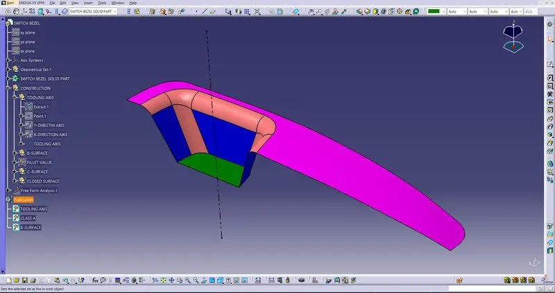
TOOLING AXIS ON CLASS-A SURFACE.
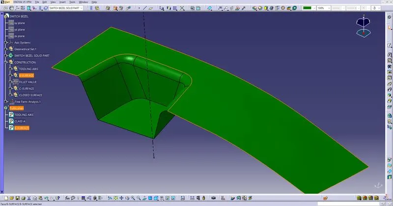
CLASS-B SURFACE CREATION.
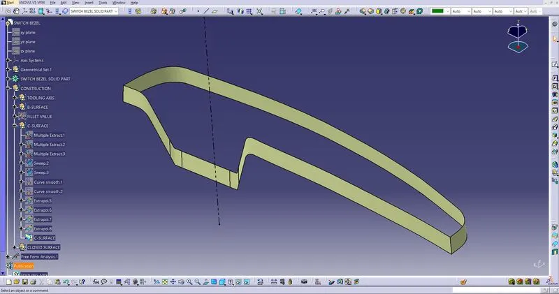
CLASS-C CREATION
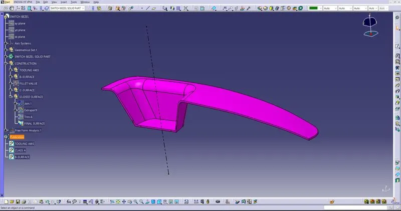
CLOSED SURFACE CREATED USING CLASS-A, CLASS-B AND CLASS-C.
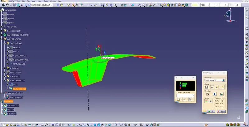
DRAFT ANALYSIS.
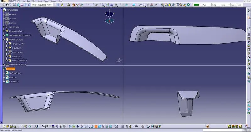
ALL VIEWS OF THE CLOSED SURFACE SOLID PART.
DRAFT ANALYSIS
- Draft of a 3 degree is to be set on the component in the direction of tooling as per the standards, this ensures the ejection of component from the mould.
- so during designing the component we should analyse the draft before the production of the component.
- In CATIA V5 we have an option called draft analysis or feature draft analysis, through which we can check and edit the component as per the design parameters.
- But for using the Draft Analysis we should determine and create the TOOLING AXIS.
- For creating a proper tooling axis there are some steps we should follow.
TOOLING AXIS CREATION BY BISECTING
- First take a point on the most suitable surface (on the bottom srurface in the above CLASS-A), then in the sketcher intersect the CLASS-A with the sketching plane and use the parallel walls to create two lines. Then using Bisecting Lines create an Axis.
- Do this in both X & Y direction, then you will have two axis.
- Now bisect both the lines Using Line-Line-Point Bisecting Option in CATIA.
- After the above Step the Tooling Axis is Created. Use this to draft analysis and also for sweep to create CLASS-C surfaces.