Design of a Base Bracket in Cars
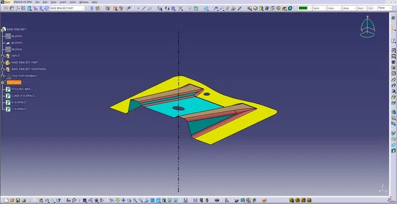
CLASS-A SURFACE
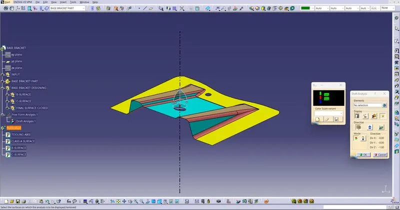
DRAFT ANALYSIS OF CLASS-A SURFACE
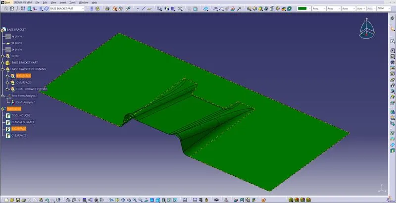
CLASS-B SURFACE
CLASS-C SURFACE
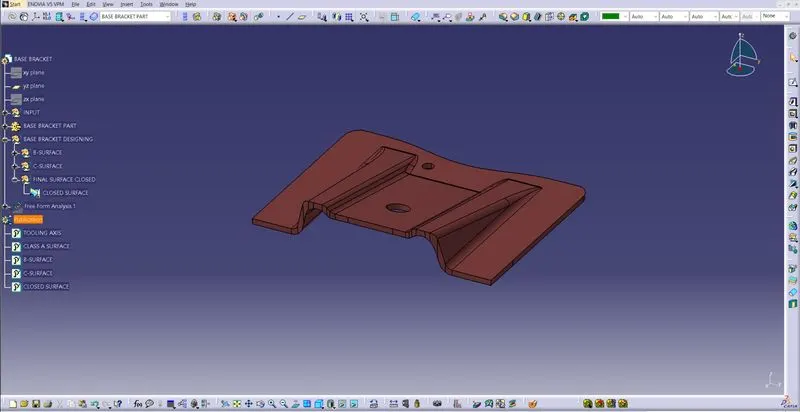
CLOSED SURFACE
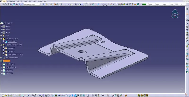
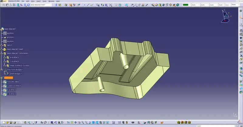
CLOSED SOLID PART
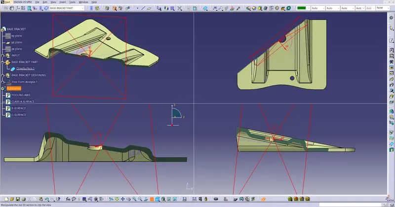
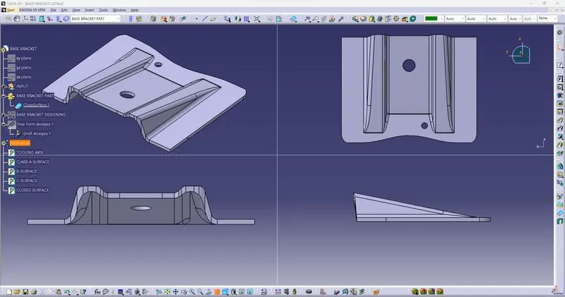
DRAFT ANALYSIS
Creating Tooling Axis
- For Draft analysis of the surface first we need to create a Tooling axis.
- So we start with a new geometrical set and name it as TOOLING AXIS. Now lets determine the direction of the Tooling Axis (Direction-Z for this perticular surface).
- When there is a Hole in the component the direction of the Tooling Axis will be Normal to the Hole as there will be another core introduced.
- After Determining the direction of the Axis we will create a Dummy axis line Normal to the Hole on the component then create a Plane on YZ and intersect the component and we will get 2-D Lines of the Component on the plane of the Dummy Axis.
- Next Step is to create Lines on the surface that are parallel to the Dummy axis, after that create a line by Bisecting both the Lines with a point in centre. This Line is the Tooling axis for this component
Draft Analysis
- Now from the Toolbar Select Insert > Analysis > Feature Draft Analysis.
- Change Shading to Costomized view parameters, then go to Material mode.
- In draft Analysis Drag the Axis Bar to the Tooling Axis, and then Check Draft on the component.
- Set the Parameter as required - ex. 0-3 degrees Green above - Blue (By Default).
- You can Hide/Show the Draft analysis from the Tree Structure.