Week 9 - Project 1 - Door Trim Lower with Engineering Features
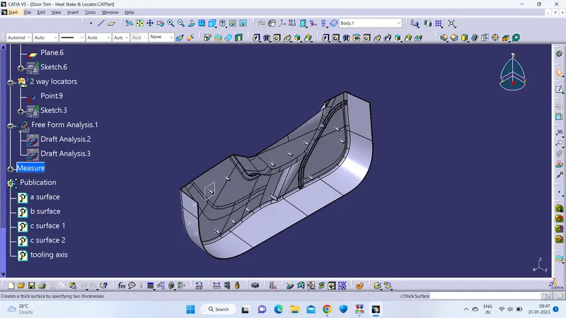
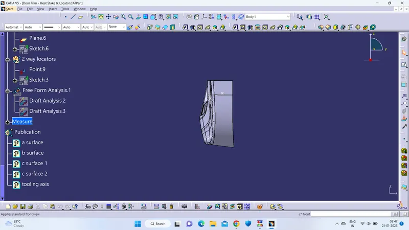
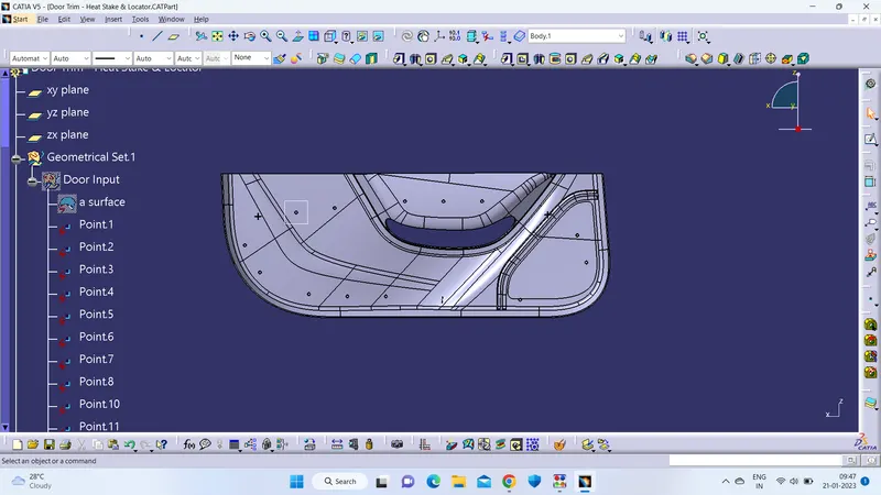
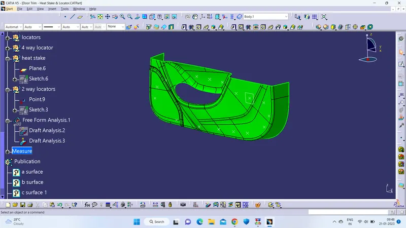
The tooling axis was created by creating a point on the surface created by taking a boundary on the inner hole and filling that boundary to form a surface. The point on that surface was created by surface option in the point definition dialog box. Then another point was offseted on the zx plane taking the inital point as reference. Then alin was formed by joining both those points together and thus the tooling axis was formed.
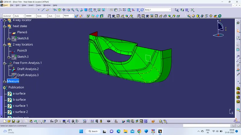
For conducting draft anlysis the tooling axis was taken as the drafting axis and then locked into place.Then the component to be analysed was taken as the body that was just formed. For the draft the axis was inverted for the proper draft to form. From the draft analysis we can see that the portion in green represents that the component has the minimum draft of 3 degrees and is ready to be manufactured. The portion in red shows that the draft is below 0 degrees.
The 4 way locators and 2 way locators were created accorfing to the design standards as given. The minimum draft for the 4 way and 2 way locators were taken to be 0.5 degrees. The height of the locators were 16 mm approximately and they were chamfered at the edges for 2 mm and then filleted for 3 mm. The the faces were filleted for 0.3 mm. These were then union trimmed with the main body. They were placed in a v shape as mentioned in the video.
The heat stakes were created using the same design standards and then they were all transalted to the points given. The external diameter was 7mm and then the internal diameter was 5 mm. These were then put together in a single body and then union trimmed with the main body.