Week 8 - Challenge 1 - Base Bracket Design
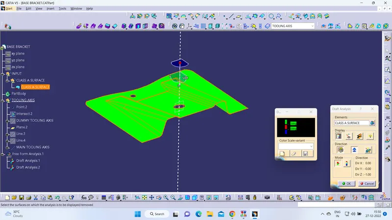
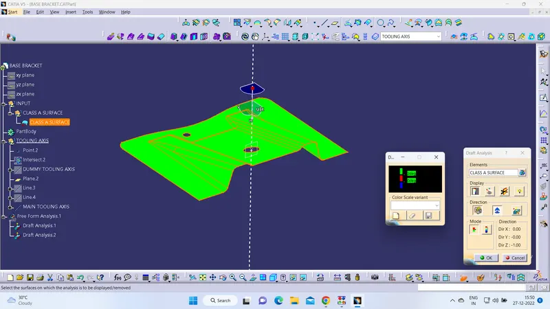
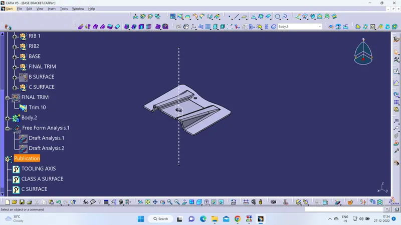
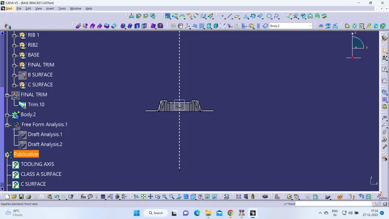
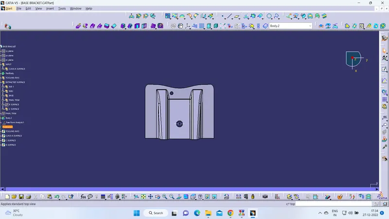
The tooling axis was created by considering the best axis for tooling and was determined to be z axis. The central hole on the class A surface was taken as the centre point for the dummy tooling axis and a line was created using the point direction method and a plane was creted with reference to y axis at that point to have the intresection sketch.
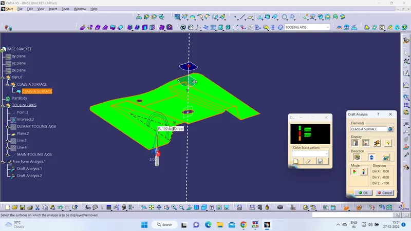
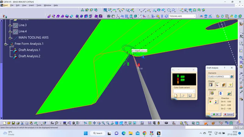
After the intersection sketch was created the drafted angle of the askecth was created using point to pint function and as extened to the required length and the line for the tooling axis was created using the bisecting functions.
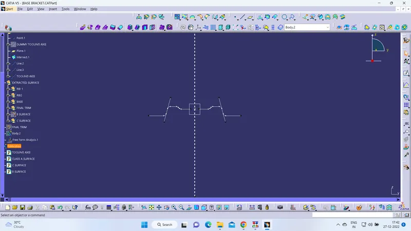
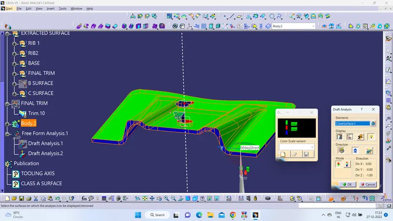
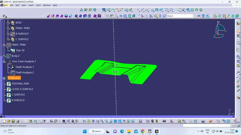
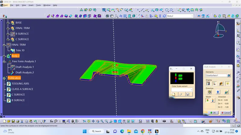
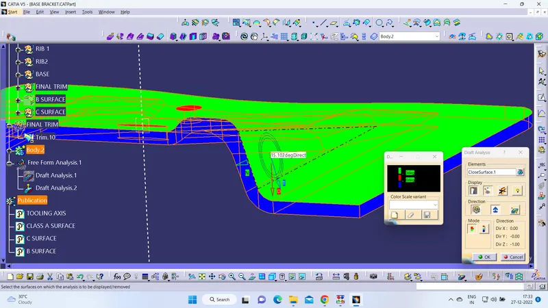
after the tooling axis was created the draft analysis was done with the minimum degree of 3 and was verified using the green color on the a surface.
subsequently the draft analysis was also done on the solid component