Week 9 - Project 1 - Door Trim Lower with Engineering Features
Aim :- The Objective Of this Repot is to Create the Door Trim Lower Plastic component with the Engineering features.
Theory :-
Heat Stakes :-
- Heat stakes usually help to assembely one component with another.
- Heat staking also known as thermoplastic staking is the process of joining two dissimilar materials together. In heat staking we use local heating and cooling to raise the temperature of plastic components and allow plastic reforming to be carried out.
Objective :-
- Check the Continuty of the Class-A
- create Tooling Axis
- Draft Analysis Of the Class-A Surface
- Create Class-B Surface
- Create Class-C surface
- Make sure for the Closed Surface
- Create Side Core Axis For Dog House
- Create the engineering Features(e.g Locator,Rib,heat Stakes,Dog House)
- Final Draft analysis of the component
Class-A Surface Continuty Check :-
- The Class-A Surface would be provided to us by the styling team of the OEM.
- Class-A surface means visible Styling surface. It gives the aesthetic of the component which is created by the styling team and gives to the part design engineer to create the part with all engineering aspects.
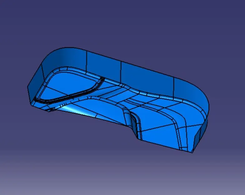
-
The first step is to check the continuity of the class A surface. This is to ensure that there is no gap between surfaces.
-
If we find any gap then we should fix that first.
-
We can analysis the class A surface through visual inspection.
-
To make sure that the given surface has no gap in between them. We can check it through the help of Join or boundary commands.
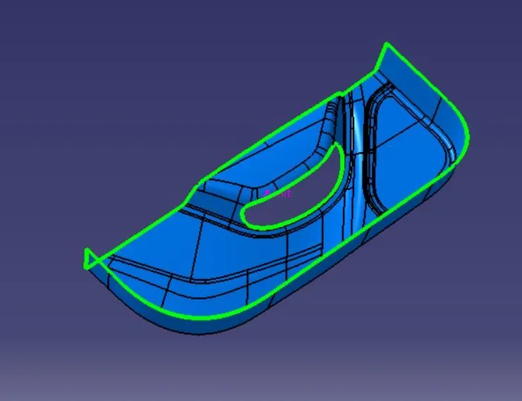
Procedure for creating the tooling axis :-
-
Tooling axis represents the opening and closing of the mold core and cavity during the manufacturing of the components.
-
A plastic product designer should consider the best tooling direction to cutdown the cost of the component very less.
-
Method opted for creating tooling axis for the bumper
- Check the best tooling direction for the given surface.
- We can find out the best tooling direction by cross checking all the three axes
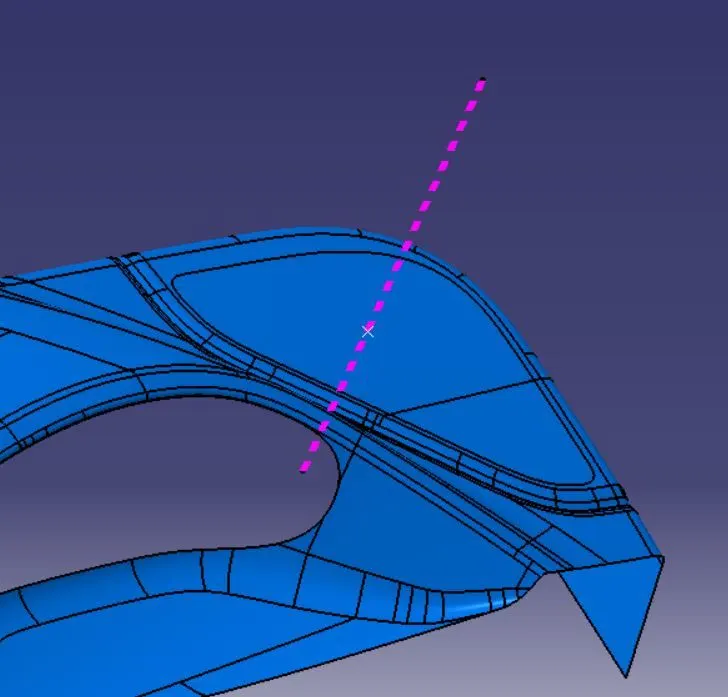
- The method choose to create the tooling axis is first extracted a surface and create a midpoint on that surface.
- The introduced an axis system on that point.
- Then created a with the point and direction along the normal to the Surface.
- Hence going with the axis created will not make any difficulties during the draft analysis.
SURFACE-B CREATION :-
-
Class-B surface means thickness of a part it is not visible and is inside part. In other words, Class-B surface is a surface below a certain thickness from the class-A surface.
-
This is the surface that contains engineering aspects of a model.
- Offset the class-A surface to 2.5mm inward direction.
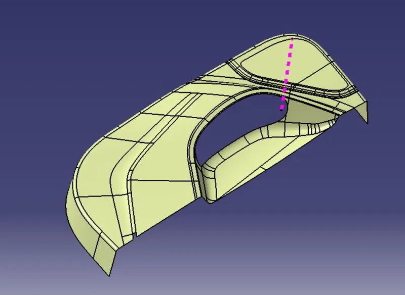
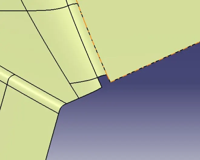
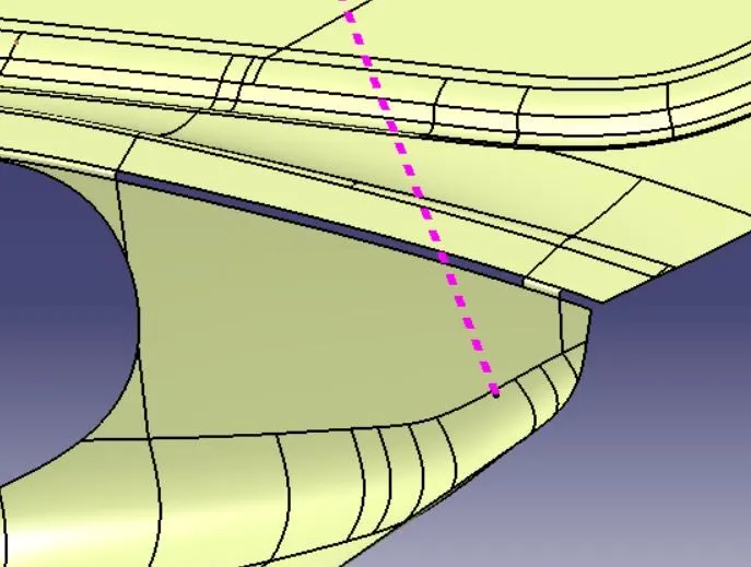
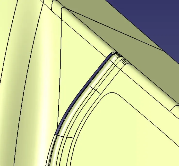
- Rework on the patches and discontinuity of the offset surfaces using the features like extract, multi-extract, sweep, multi-section surfaces, extrapolate.
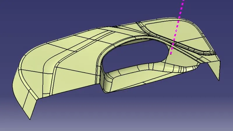
- To ensure the continuity of the Class-B surfaces check the boundary command to find out the boundary.Hence class-B surface creation is done.
Surface-C Creation :-
-
The Surface that joins class-A and class-B surfaces is called as class-C surface.
-
Class C is often specified for interior surfaces not readily visible, surfaces that will be covered by another part when assembled.
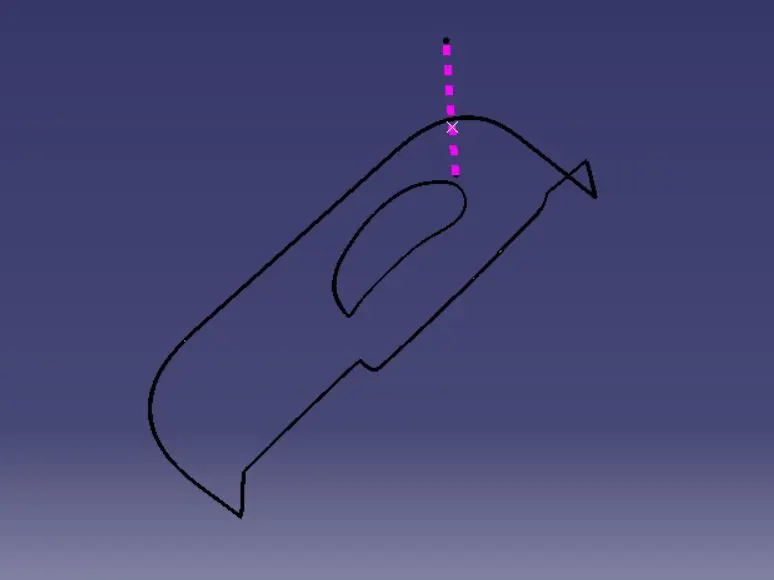
Since it is a complex class-A surface, we cannot simply create the class-A boundary curve and sweep it at one shot.
-
Hence, we need to create smaller curves using boundary command and then create sweep of 93 degree or 87 degeree accroding to the direction with reference to the surface option.
Creating the final closed Surface:-
- First step is to join the CLASS-A surface with CLASS-C surface.
- Then Trim the Joined surface with CLASS-B surface to achieve the final door trim lower surface.
- Switch to the part design work bench and using the close surface command to create the door trim lower solid part.
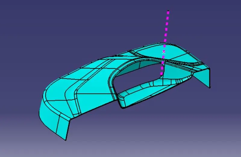
Draft Analysis :-
Class-A Surface :-
-
The Draft Analysis is a command enables you to detect if the part you drafted will be easily removed or Not.
-
This type of analysis is performed based on colour ranges identifying zones on the analysed element where the deviation from the draft direction at any point, corresponds to specified values.
-
Draft analysis is done after determining the tooling axis, draft analysis is used to check whether the minimum draft (3 degrees) is maintained or not.
Procedure for performing the draft analysis are as follows:-
- Change the view mode of the component to be in customized parameter mode and then select the shading mode as materials.
- Then open the featured draft analysis tool from the insert menu.
- Then click on use the compass to define the current drafting direction and then drag and align the compass on the Tooling axis.
- Then lock the draft direction and perform draft analysis by clicking on the component.
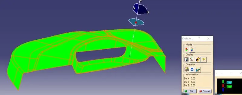
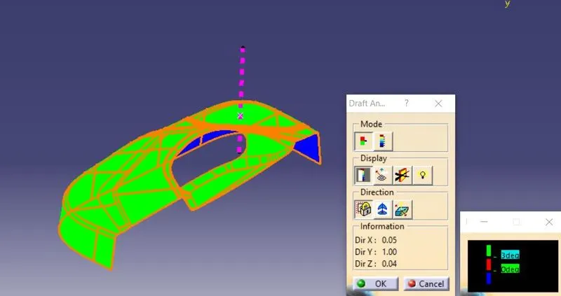
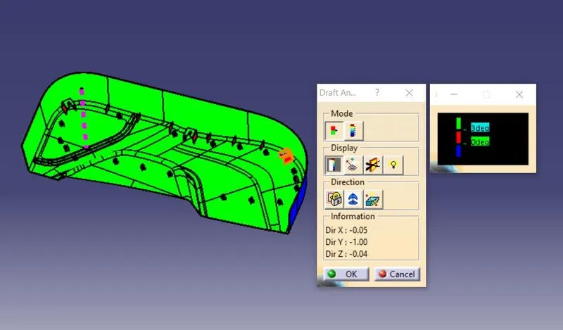
- The green colour shows the positive daft tooling direction and the given surface passes the draft analysis.
- Click on the analyses under the running point to check the draft analysis on the individual faces. It shows how much draft on specific points when we move the cursor point.
Draft analysis of Class-A:-
Draft Analysis Of final Solid Body :-
Creating the Engineerring Features :-
CREATING THE RIB:-
- Ribs are thin wall protrusions that extend perpendicularly from a wall or plane. They are usually found in clusters offering support to a plane that would have otherwise been too thick, but can also be stand-alone support for a single wall. They are commonly used to provide additional support and strength to a part. Thickness and location are essential to rib design.
- First, the base surface where the rib has to be created is extracted using the Extract command and Create a sketch as per the Rib Dimension.
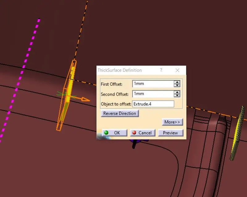
- Provide a thickness of 1mm to the Rib as per the design rule it should be 0.4 times of the thickness of the base componet .
- Give the Height of the Rib 12.5 mm which is 5 times to the thickness of the component.
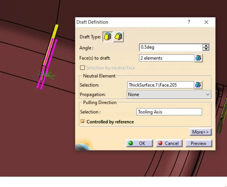
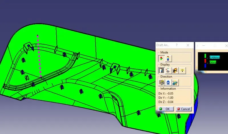
- Give a Draft of 0.5 Degree to upward direction to clear the draft Analysis.
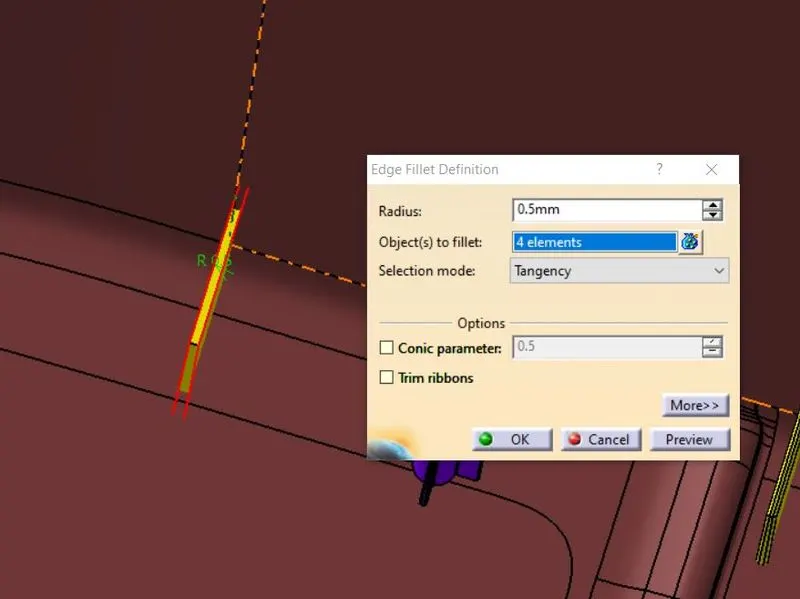
- Finally Fillet the Sharp edage with the value Of fillet Radius 0.5mm.
LOCATORS & HEAT STAKES :-
-
The locators restrict all the other degrees of freedom except the translation along the direction of tooling axis Le along y-axis. For restricting that degree of freedom we will be using the heat stakes.
-
In heat staking, we use local heating and cooling to raise the temperature of plastic components and allow plastic reforming to be carried out.
- There are certain design rule to create the locator such as thickness of the locator,draftangle,height of the Locator.
- we keep the locator height higher than the heat stakes because locator reduce the degree of freedom of the Component.
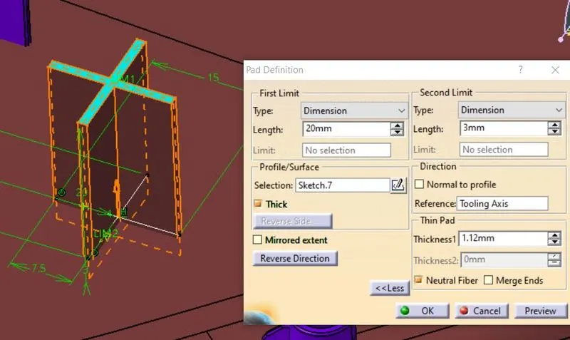
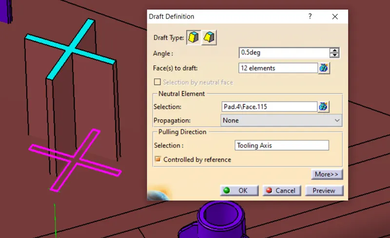
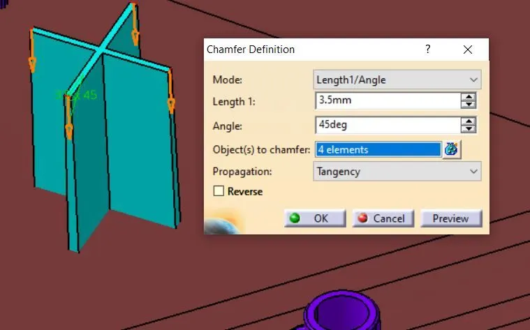
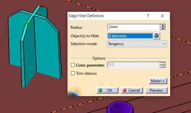
- Then we create the heat stakes, it will enter the mating component and using a heat staking machine these heat stakes are melted and cooled.
- When cooled this will get hardened and the two components will stick together. Thus all degrees of freedom are arrested.
- There are certain design rule to create the heat stakes such as thickness of the locator,draftangle,height of the Locator.
- we keep the heat stakes height lower than the locator so that locator first fix the component with the parent body after that only one degree of freedom will be remain along the longitudinal axis of the heat stakes then heat stakes fix this degree of freedom.
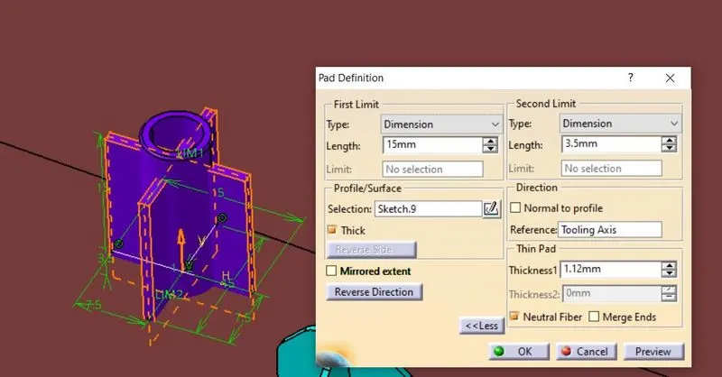
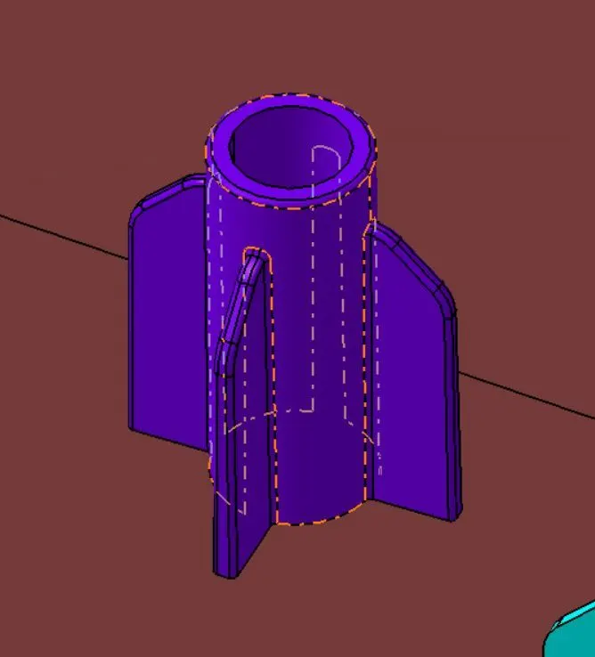
- we provide supports to the heat stakes by 4 Rib.
- Keep the Height of the Heat stakes 18 mm which is lower than the Locator.
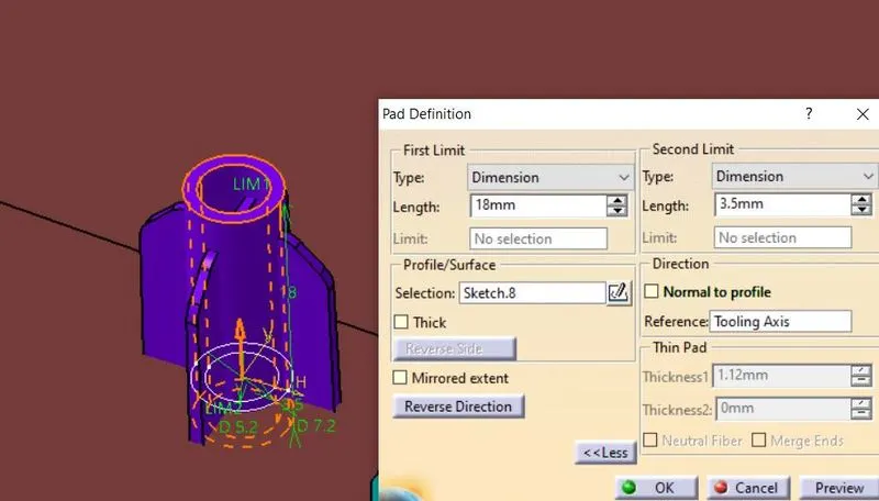
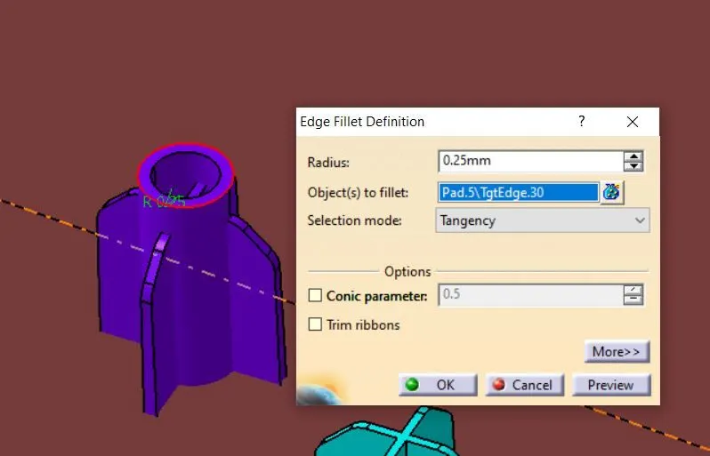
Cearting the Support Rib For the heat stakes.
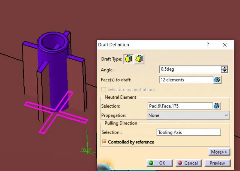
Provide draft of 0.5 degree to the ribs.
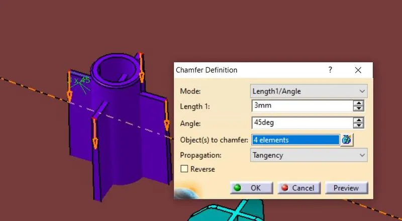
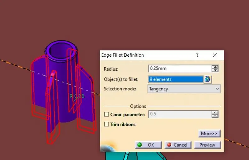
Final heat stakes
Dog House Creation :-
-
The dog house is an engineering feature used in the plastic trim design. Dog houses are used as a supporting feature. Sometimes other engineering features like snaps; locators, etc. are mounded on them to increase their strength.
-
The doghouse is created by following the design rules.
-
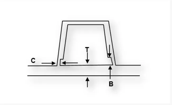
The nominal wall thickness guide range is from 0.75 mm to 3 mm for reinforced materials and 0.5 mm to 5 mm for unreinforced materials.
-
Doghouse wall thickness at the intersection of the part wall ( C ) should be 40% or less than the main wall stock ( T ).
-
The height of ( B ) should be between 3.0 – 6.0 mm
-
Minimum width of the dog house is 12 mm.
-
Minimum draft for the do house is 1.5 degree to die draw.
Procedure to Create the Dog House :-
- First step is to create a side core axis.
- I have chosen normal to the point method for creating the side core tooling axis.
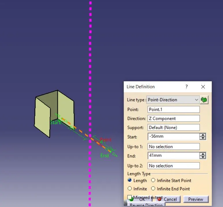
Create the sketch and sweep it as per the design rule
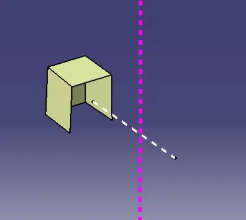
Create the cut mark on the Bottom part of the dog house to prevent fom sink mark in the class-A surface
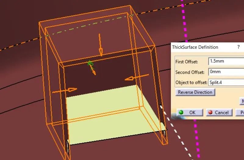
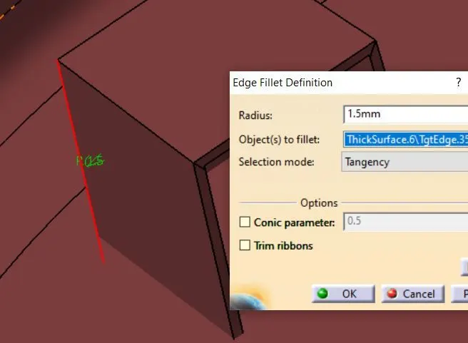
Give the Edage fillet radius value that is 1.5mm as per the design rule
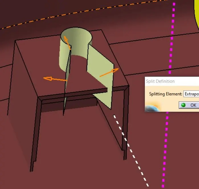
All the Engineering Feature is created now we go for the Draft analysis for the Part Body:-
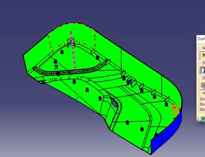
At the draft angle of 3 degree
A draft angle .49 degree
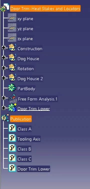
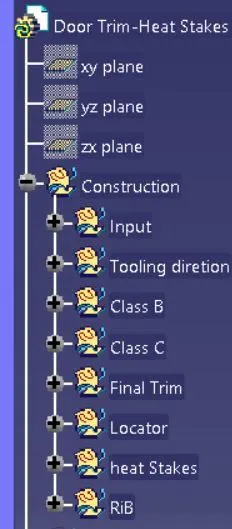
Tree Struture :-
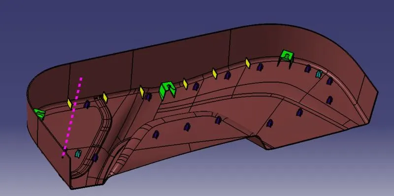
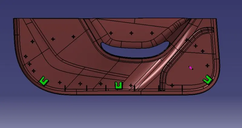
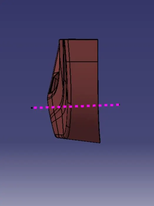
All the View :-
isometric :-
Top view :-
Side View :-
Conclusion :-
Learn all the things which we consider while making the project in the catia and also learn design rule used while create the Dog house, Rib And Heat stakes . now the door trim lower part is created sucessfully.