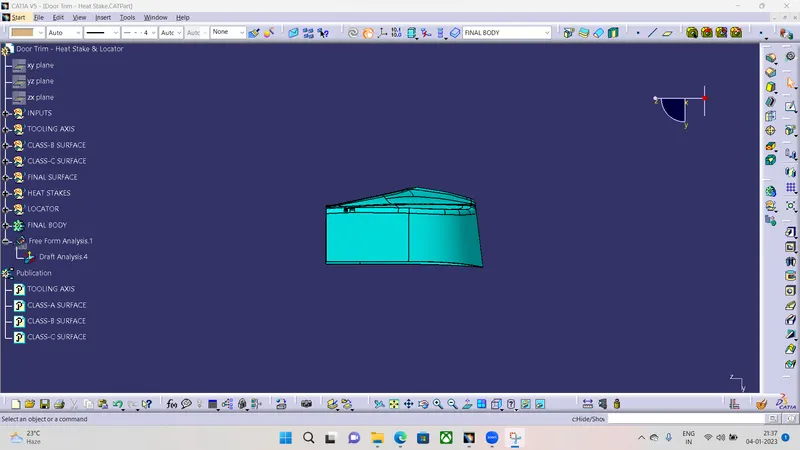
Week 9 - Project 1 - Door Trim Lower with Engineering Features
DOOR TRIM WITH ENGINEERING FEATURES
Aim
- To craete a Closed Surface and Add Engineering features to the door trim and perform Draft analysis on the Component.
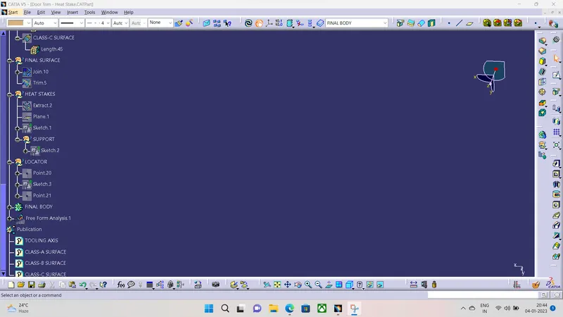
TOOLING AXIS
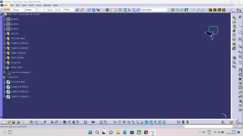
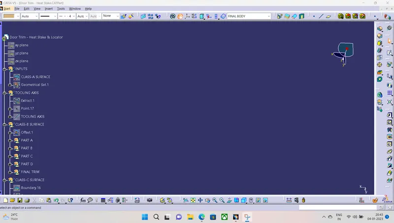
- The tooling axis for this Door trim is we are taking a Normal to a Surface.
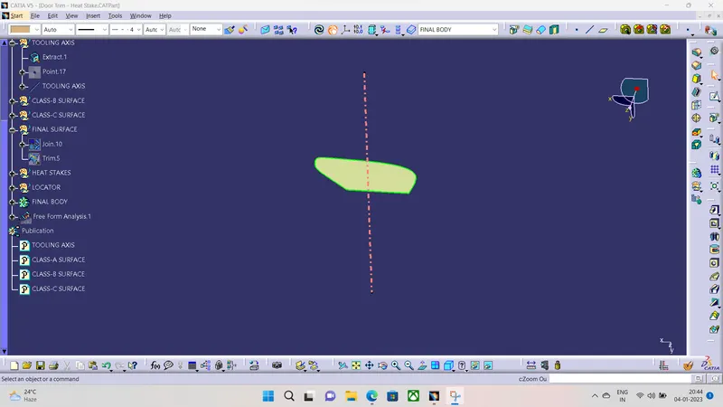
Class-A Surface
- We are going to perform Draft analysis on the given Class-A surface.
Class-B Surface
- We are Going to Offset the Class-A surface to 2.5MM and we will solve the patches formed on the offsetted surface.
- We will extract and Extrapolate and perform trim operation and fonally extra polate the boundaries for the final procedure.
Class-C Surface
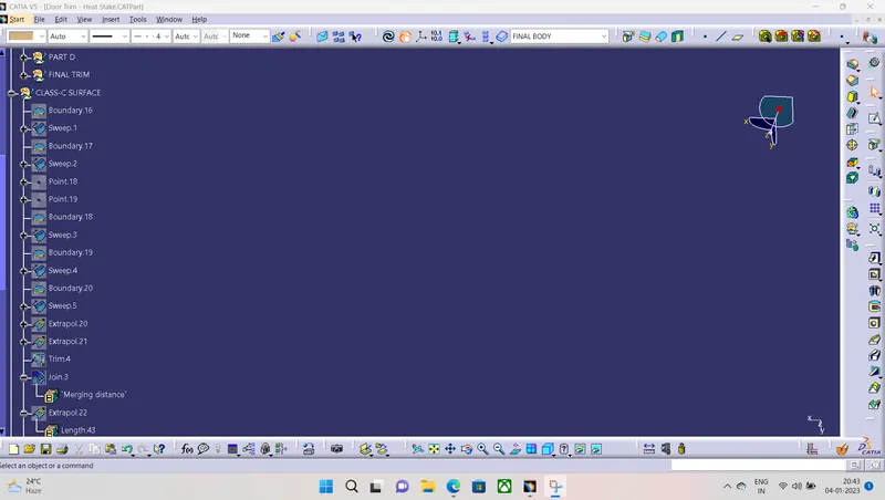
- We will Create the Class-C surface by Two methods Wit Reference to Class-A Surface.
- 1)If the Surface is Parallel to Tooling Axis We will use Sweep with Draft Direction at 3.
- 2)If surface is Perpendicular to Tooling Axis we will use sweep with reference surface at 90°.
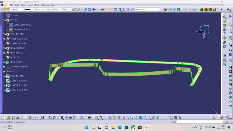
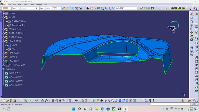
Final Surface
- We are going to Join Class-A and Class-C first and Then Trim With Class-B.
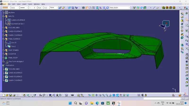
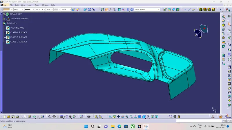
Closed Surface
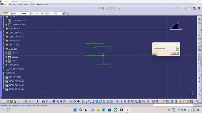
Locators
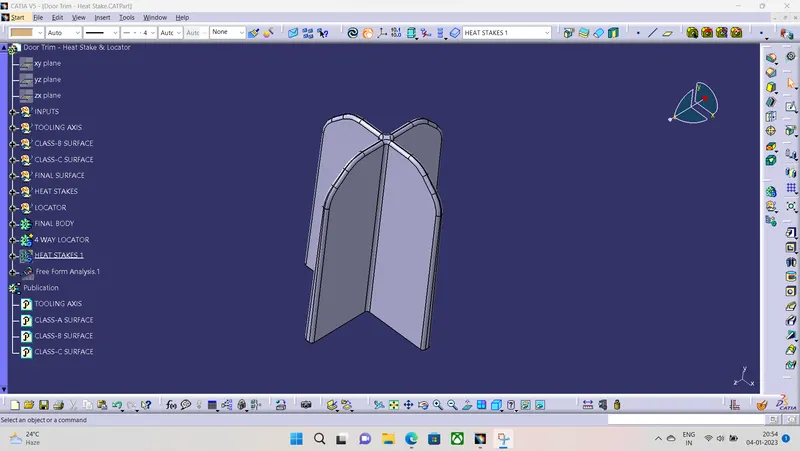
- I have Created a 4-way Locator of 2MM thickness and padded it to a 20MM from Class-A surface and Gave a Draft of 0.5
- We will give a Fillet radius of 0.3MM.
Heat Stakes
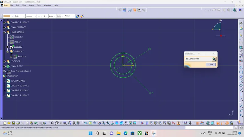
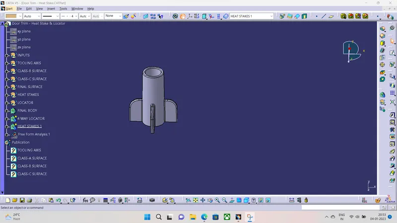
- I have created a Circle of D7MM and a Hole of D5MM and Padded it to 18MM as it should be Less Than Locators a First loctors are Fixed and then Heat stakes.
- We hav given Draft of 0.5°.
Support Rib For Heat Stakes
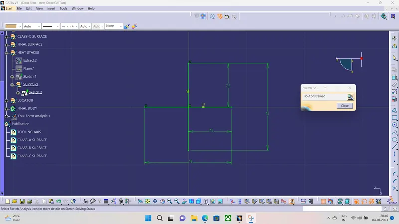
- Creation of this as same as Loctar but we Are padding it to a 8MM.
Final Heat Stake
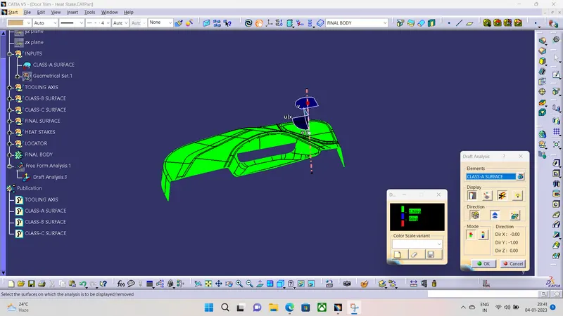
Draft Analysis
- We are going to perform Draft analysis on the Closed Body and Heat stakes and Locators.
- For the Closed Body we will perform Draft analysis between 0°-3°.
- For the Locators We will perform Draft analysis between 0°-0.5°.
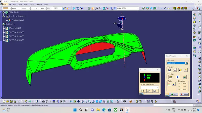
Draft analysis on Heat stakes and locators
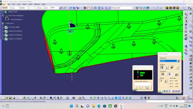
Hence our Analysis is within our Given Design Rules
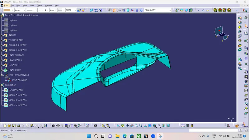
Isometric View
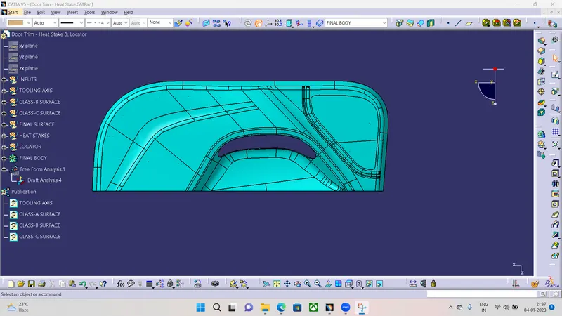
Top view
Front view
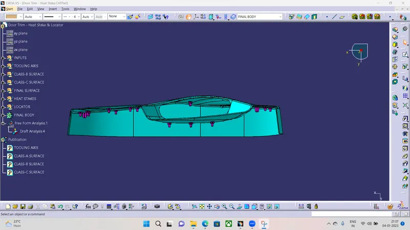
Side View