Week 8 - Challenge 6 - Core & Cavity Design
DESIGN OF CORE AND CAVITY BLOCKS
Aim
- The aim of the project is to create the core and cavity block and perform draft analysis on the switch bezel component.
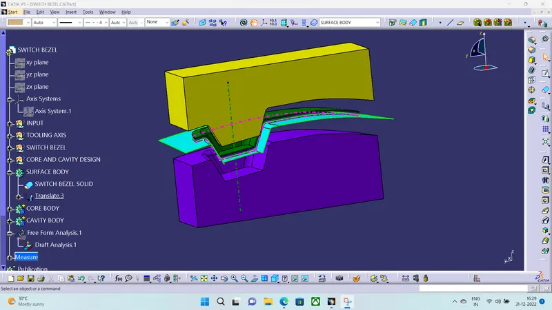
- Below is the tree structure for the creation of core and cavity block.
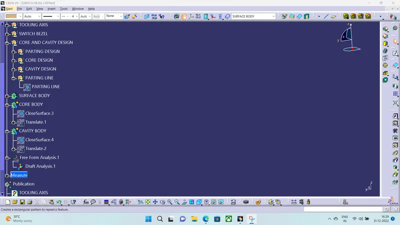
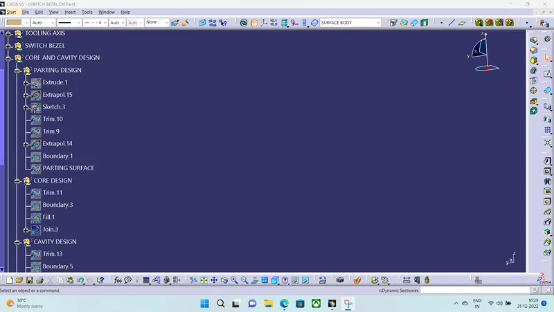
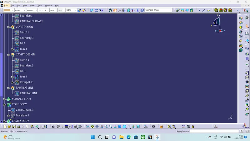
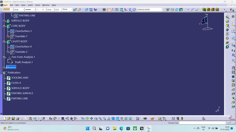
Tooling axis
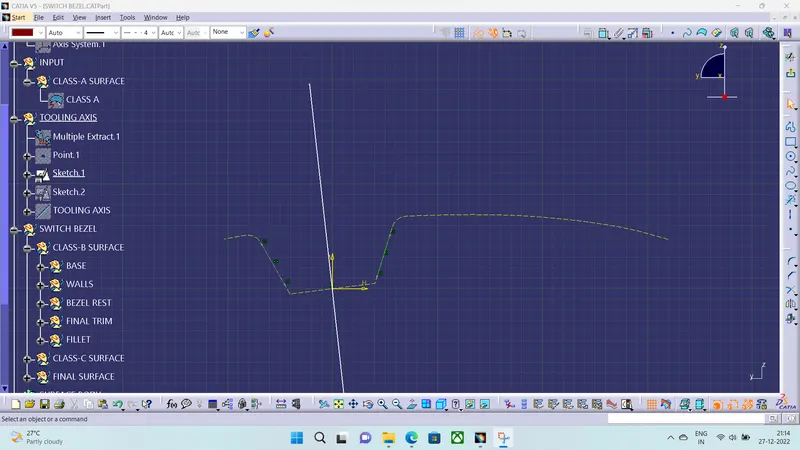
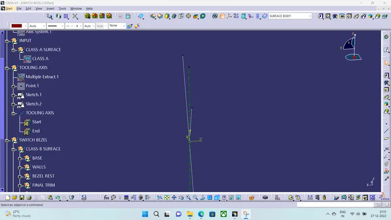
- For the creation of tooling axis we are going with the bisecting line method because when we look at in Y direction we are observing two lines which are at a certain angle and if we find the bisecting line in this direction we can see every part of the componenet.
- After creating this line we are going in Xdirection to see any lines are at a certain angle and there is only one lin and we are going to create line at 6° normal to axis system which we created on the class-A surface.
- After this we are going to find the bisecting line between the Y direction line and X direction line and in this way we will get our Tooling axis and if we view from this we can see the Draft angle on the component.
Class-A surface
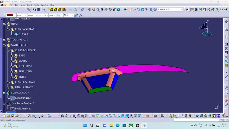
- The Class-A is provided by the OEM's and we will Convert this it into Closed Surface.
Class-B surface
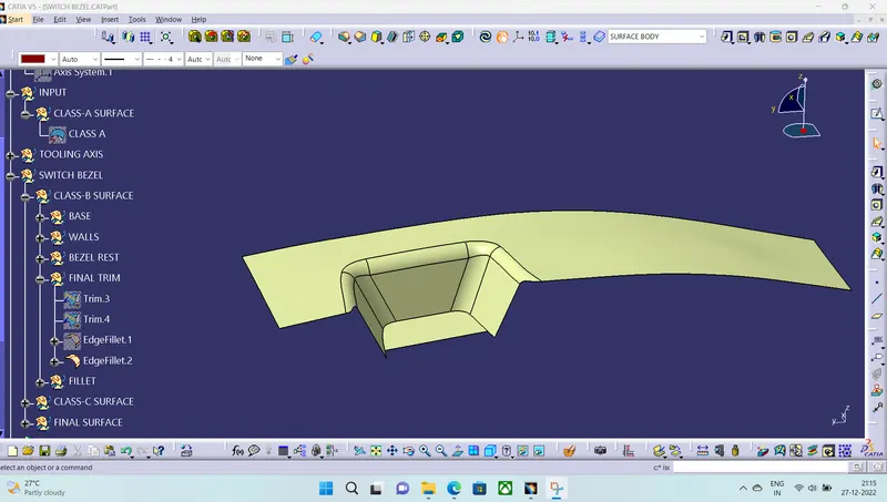
- The Class-B surface is Created from offsetting the Class-A surface to 2.5MM and we have to solve some patches by extrapolating and trimming it and then we apply fillets.
Class-C surface
- This surface is Created from the Class-A with Sweep along with Draft direction at 3°.
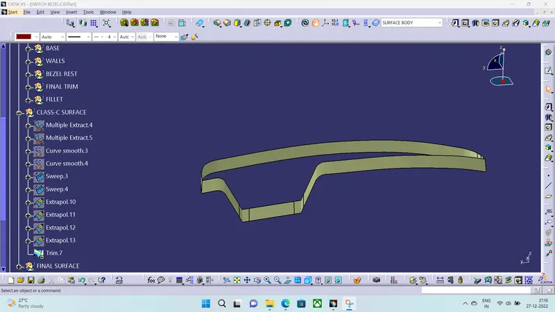
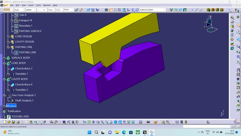
Creating the Core and Cavity
- For creating the core and Cavity We are taking the Class-A, Class-B and Class-c surfaces.
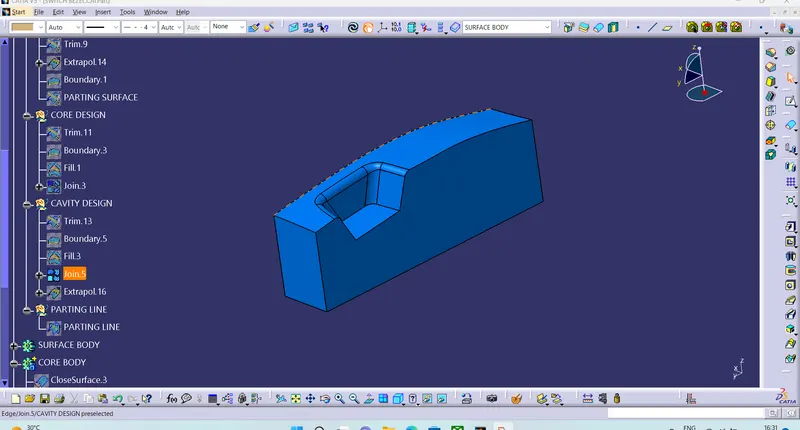
- First we are trimming the Class-A and Class-C and Then Class-B and We will get the Closed Surface after this we are going to create a sketch on YZ plane and Extruding to a Certain length.
Core Design
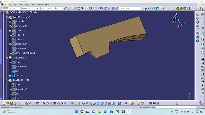
Cavity design
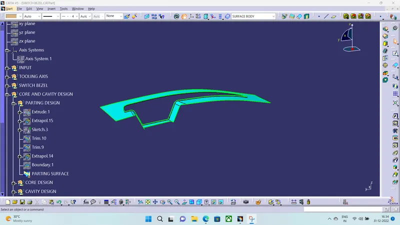
Parting surface
It seperates the the Class-A and Class-B surface and it is formed on B side surface.
Parting line
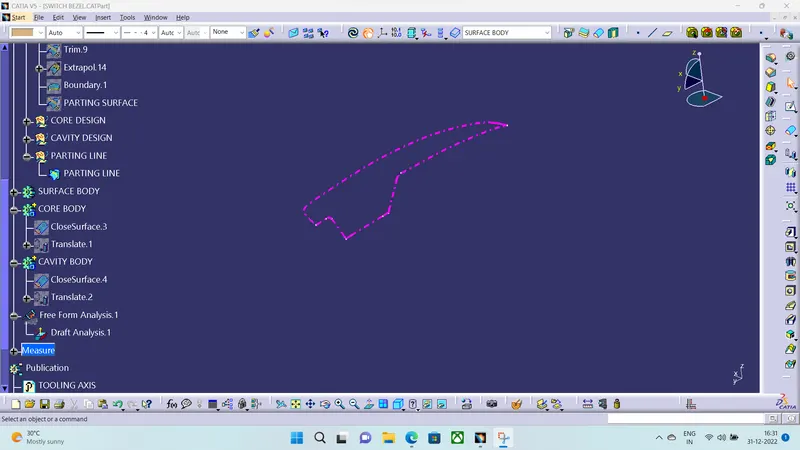
- Which Seperates the Componenet and Parting Surface.
Draft Analysis on the Switch Bezel
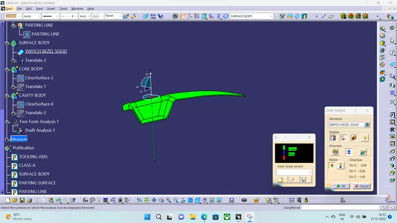
- The draft analysis is performed to check Whether our component is clearing our desirable Design rules while manufacturing the component in the core and cavity block.
- The Draft angle is between0°-3°.
- We will check the draft angle along the Tool axis.