Week 8 - Challenge 2 - Switch Bezel Design
SWITCH BEZEL
- Observing the given Class-A Surface and dividing it into seperate parts.
- Now we have to find the Tooling Axis for the Component as per Design rules.
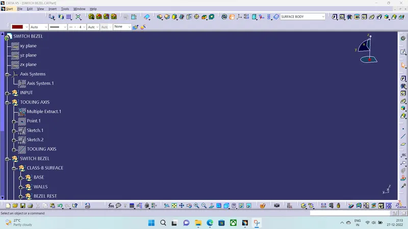
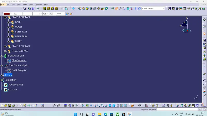
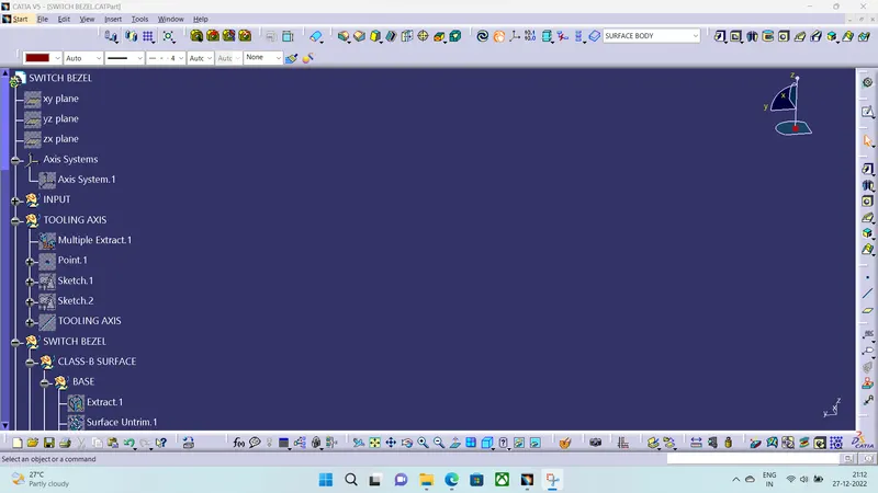
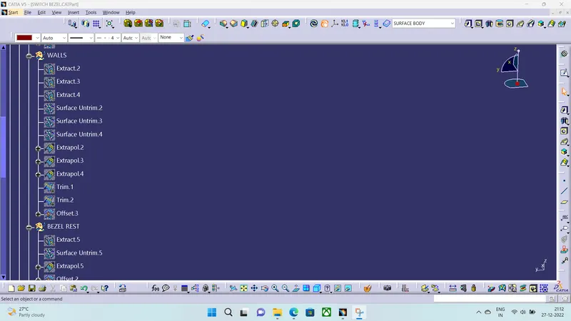
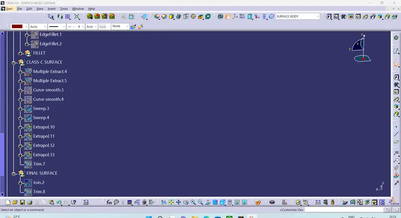
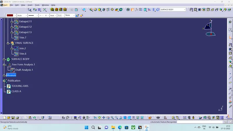
CLASS-A SURFACE
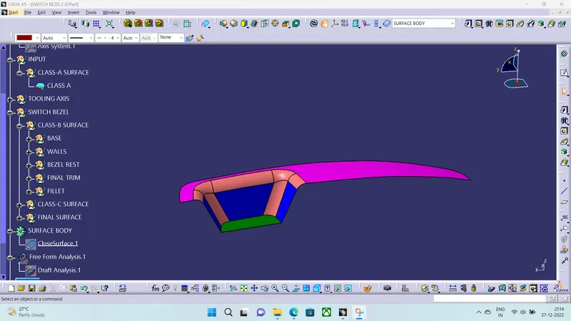
- for the given Class-A we have to give a thickness value of 2.5MM and for this we seperating the surface ainto different parts.
- we will create a Class-B and Class-C surface.
- Before this Tooling Axis is Created.
TOOLING AXIS
- First we are Creating a dummy axis on YZ-plane along the Bisecting line of the Switch Bezel.
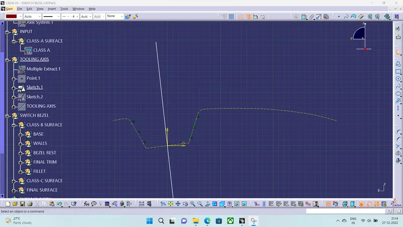
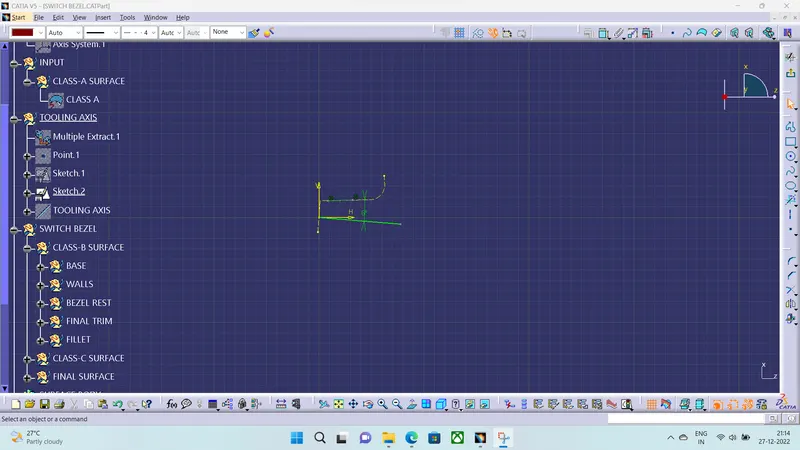
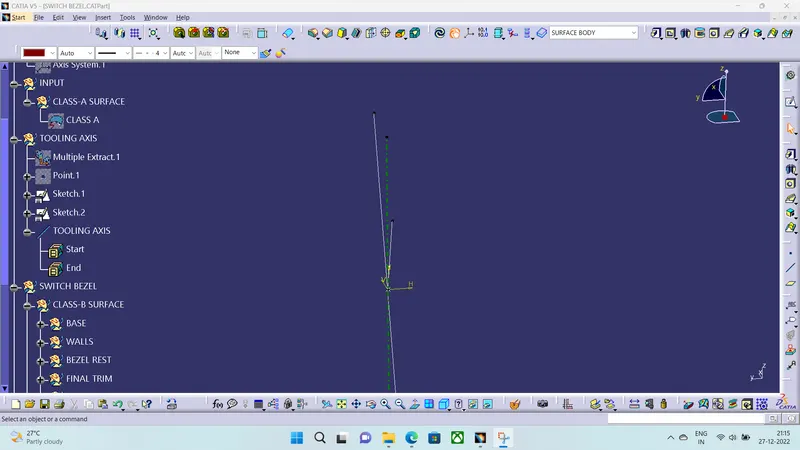
- After Creating the line at a 6° in the ZX-Plane , we are gonna Create Bisecting line and THis line will become our Tooling Axis.
CLASS-B SURFACE
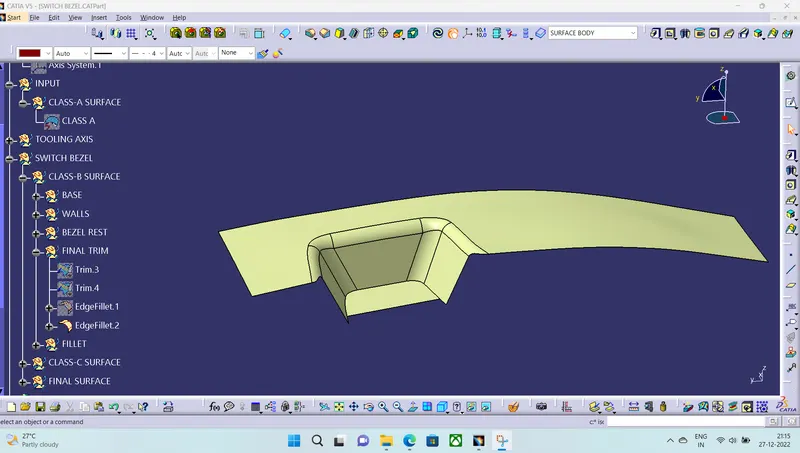
- Class-B surface is Obtained by Various operations of Surface Workbench.
CLASS-C SURFACE
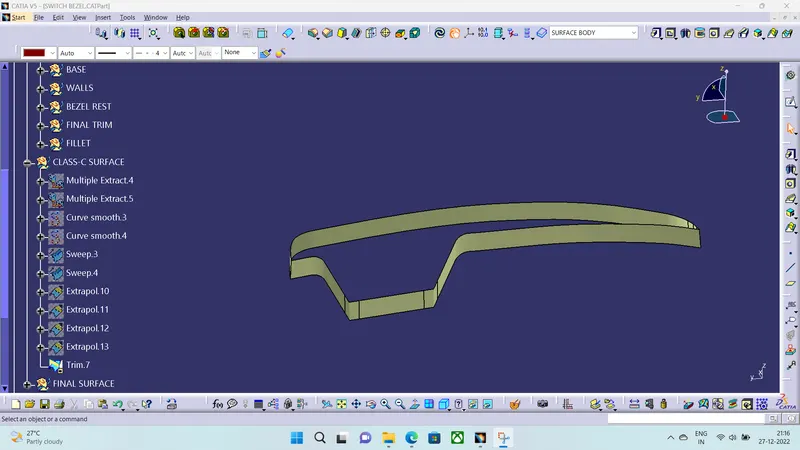
- Class-c is Obtained by the Boundary of Class-A Surface and we will use Sweep operation along the Tooling Axis With Draft Angle 3°.
FINAL SURFACE
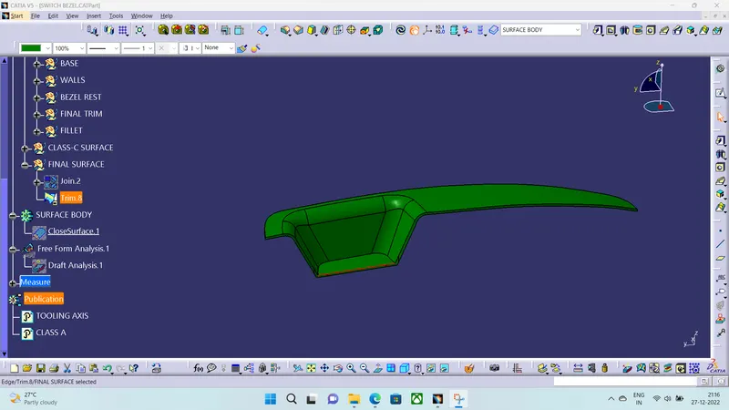
CLOSED SURFACE
ISOMETRIC VIEW
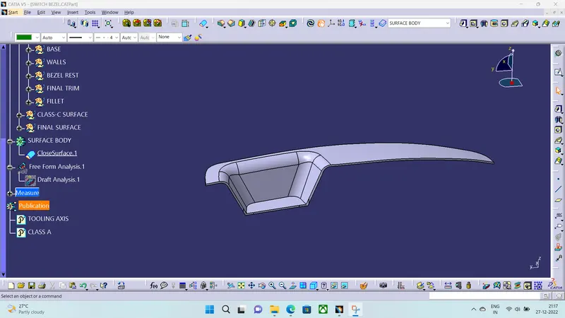
FRONT VIEW
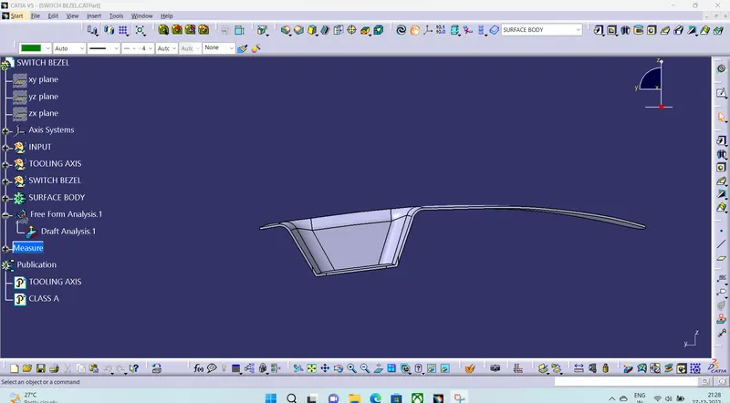
TOP VIEW
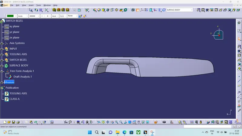
SIDE VIEW
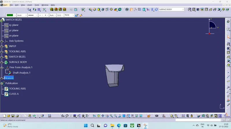
DRAFT ANALYSIS
- For checking the draft analysis we take tooling direction to check the draft angle which is between 0°-3° and it should satisfy the conditions.
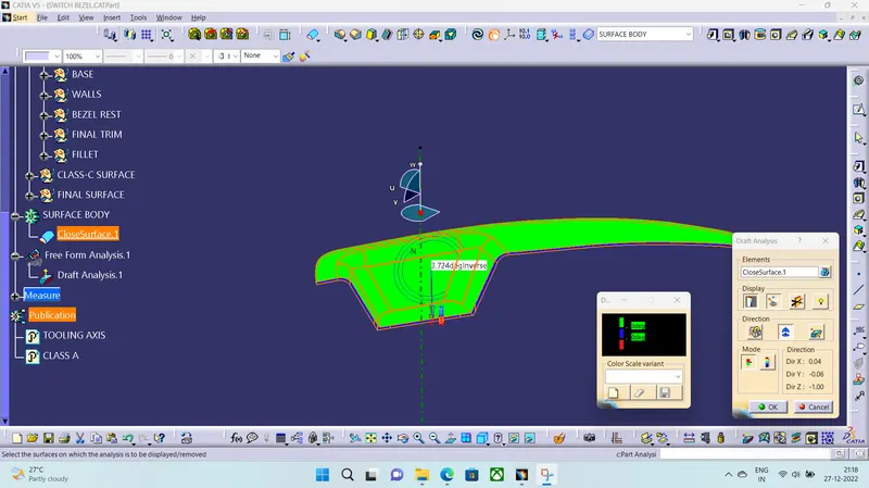
- Hence our switch bezel is within our draft analysis.